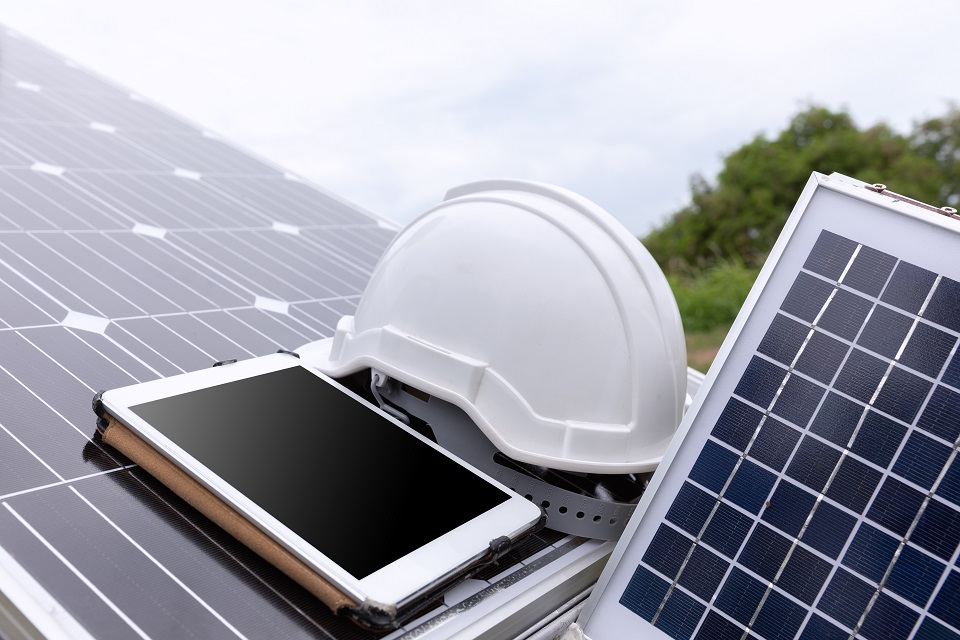
How to Prevent Corrosion on Polycrystalline Photovoltaic Panels
Apply anti-corrosive SiNx coating (75-85nm thick) to block moisture; keep ≥10cm installation gaps for airflow; rinse quarterly with deionized water to prevent electrolyte buildup, reducing corrosion risk by 40% over 5 years.
Site Selection and System Design Phase
The foundation for a photovoltaic power plant's 25-year long lifespan is laid during the site selection and design phase. Neglecting corrosion protection, especially in the early stages, can lead to a sharp system efficiency decline of 10%-30% within 5-8 years, and even pose structural safety hazards.
Data shows that in coastal areas with high salt spray, the corrosion rate of ordinary carbon steel brackets without proper protection can be as high as 0.1-0.2 millimeters per year, meaning critical load-bearing modules could corrode through within 5 years.
An upfront investment in anti-corrosion measures, accounting for about 3%-5% of the total budget, can increase the system's effective lifespan from the 10-year level to over 25 years, boosting the internal rate of return by 2-5 percentage points.
Quantitative Assessment of Environmental Corrosivity
During the 25-year lifespan of a photovoltaic power plant, environmental corrosion is a silent "asset depletor". A common mistake is judging based solely on vague descriptions like "near the sea" or "has factories," which can lead to either insufficient or excessive anti-corrosion measures, resulting in tens of thousands or even hundreds of thousands of RMB in annual power generation losses or additional costs.
Data indicates that using bracket designed for C2 (medium corrosion) standards by mistake in an unassessed C4 (high corrosion) environment can lead to an actual corrosion rate 5 times faster than expected. This could necessitate structural module replacement as early as years 8-10 of the project's operation. The single replacement cost might exceed 15% of the initial investment, with downtime causing generation losses over 200 RMB/kW/year.
1. How to Measure Salt Spray Concentration? Target the Chloride Ion Culprit
· Step 1: Check Distance, Set the General Direction. The risk increases exponentially the closer you are to the coastline. Typically, 5 km is the first critical threshold. Areas within 5 km must initiate detailed monitoring. Within 1 km, the highest anti-corrosion grade (C5-M) should generally be adopted directly.
· Step 2: Use Professional Methods to Measure Deposition Rate. Distance isn't precise enough; you need to measure the Chloride Ion Deposition Rate in the atmosphere, in units of milligrams per square meter per day (mg/m²/day).
o Operation Method: Deploy "wet candle" collectors or standard plate collectors on-site, expose them for 30 days (a complete tidal and meteorological cycle), then analyze the chloride ion content in the collected liquid using laboratory ion chromatography.
o Data Benchmarking and Decision Making:
§ < 60 mg/m²/day: Corresponds to C3 (Medium) environment. Standard hot-dip galvanizing (thickness ≥65μm) can handle this.
§ 60 - 300 mg/m²/day: Enters C4 (High) corrosion grade. Requires thicker galvanized layer (≥85μm) or consideration of aluminum alloy.
§ > 300 mg/m²/day: Belongs to C5 (Very High) corrosion grade. Must consider 316 stainless steel or dual protection with galvanized layer + anti-corrosion coating.
· A Specific Scenario: A plant located 3 km from the coast but downwind of the prevailing wind might measure a chloride deposition rate of 450 mg/m²/day, far exceeding the C5 lower limit. Another site only 800 meters from the coast but shielded by a small hill might measure only 150 mg/m²/day, belonging to C4.
2. What About Industrial Areas? Focus on SO2 and pH
· Sulfur Dioxide (SO2) is the Primary Indicator: SO2 dissolves in water to form sulfurous acid, a main module of acid rain. Check the annual average SO2 concentration (μg/m³) published by local environmental authorities.
o Safety Line: Concentration below 10 μg/m³, corrosion impact is negligible.
o Warning Line: When the concentration is between 10 and 50 μg/m³, corrosive begins to appear, requiring targeted measures in material selection, such as ensuring the quality and integrity of the zinc plating.
o Action Line: Long-term concentration > 50 μg/m³, environmental corrosive jumps significantly. The galvanized layer on support materials needs thickening, and special attention should be paid to the protection of connecting pieces, as acidic environments accelerate the degradation of ordinary steel fasteners.
· Rainwater pH Value, Measures Actual Acidity: Atmospheric SO2 concentration is the "cause," rainwater pH is the "effect." Collect monthly rainwater samples and measure their pH.
o Normal rainwater pH is about 5.6.
o When pH consistently falls below 5.0, it indicates severe acid rain. For every 1 unit decrease in pH, hydrogen ion concentration increases 10-fold, roughly doubling the corrosion rate of metals. In areas with pH 4.0-4.5, the corrosion rate of ordinary steel can be 3-5 times that in neutral areas.
3. How to Use Humidity, Wind Speed, and Temperature Difference Parameters?
· Annual Average Relative Humidity (RH) is Key: When metal surface temperature drops below the dew point, moisture condenses. Even if RH is below 60%, radiative cooling of the metal at night can cause condensation. But if the annual average RH > 60%, especially > 80%, a continuous liquid film exists on the metal surface, and corrosion proceeds continuously. In hot, humid summers, the corrosion rate can be 5-8 times that of the dry winter period.
· Wind Speed and Direction: Wind speed affects the transport distance and deposition location of salt spray and pollutants. The windward side facing the prevailing wind has significantly higher corrosion risk for modules and bracket than the leeward side.
· Temperature Fluctuation: In regions with large daily temperature variations (e.g., daily range > 15°C), thermal expansion and contraction accelerate the aging of anti-corrosion coatings (paint, plating), creating micro-cracks that allow corrosive media to penetrate.
4. Final Decision: Synthesize All Data, Include a Margin
1. Grade According to ISO 9223 Standard: Input the measured chloride, SO2 concentration, and humidity data into the corresponding table of ISO 9223 to obtain an official corrosivity grade (C1-C5).
2. Upward Rounding Principle: If the data is near the borderline between two grades (e.g., just meeting the C4 lower limit), especially for PV plants planned to operate for over 25 years, it is recommended to proceed with material selection and anti-corrosion design according to the next higher grade (C5). Increasing the upfront investment by 3%-5% can avoid large-scale replacement at the critical 10-15 year mark, offering a very high cost-benefit ratio.
3. Establish a Site Corrosion File: Archive the initial environmental monitoring data, material selection basis, and anti-corrosion design standards. This not only reflects engineering standards but also provides baseline data for evaluating maintenance effectiveness 10, 15 years in the future, accurately verifying the correctness of current decisions and providing a valuable database for subsequent projects.
Cost of Material Selection
A common mistake is comparing only initial purchase prices: hot-dip galvanized steel costs about 7000 RMB/ton, aluminum alloy is about 2.5 times that, and 316 stainless steel reaches 18000 RMB/ton.
In a coastal C4 environment, a poor-quality galvanized bracket might start showing rust spots by year 8, requiring investment of 30%-50% of the initial cost for local reinforcement or replacement by year 12, with an average annual power generation loss of about 5%.
In contrast, a qualified 316 stainless steel bracket can have maintenance costs controlled within 2% of the initial investment over 30 years. Behind this lies the precise calculation of Levelized Cost of Energy (LCOE). The goal is not to save 200,000 RMB today, but to avoid 2 million RMB in future losses and generation revenue shortfalls.
1. Hot-Dip Galvanized Steel: The Economical and Durable First Choice, but Details Determine Success
Galvanized Layer Thickness is the Lifeline: Never settle for the vague concept of "it's galvanized." You must explicitly require the average thickness and local minimum thickness of the zinc coating.
C3 Environment (Inland Ordinary Industrial/Urban): Double-sided average thickness should be ≥ 65μm (equivalent to zinc coating mass ≥ 460g/m²). Theoretically, this standard can provide 15-20 years of protection against red rust.
C4/C5 Environment (Coastal, High-Humidity Industrial Areas): Double-sided average thickness must be ≥ 85μm (zinc coating mass ≥ 600g/m²). Increasing the thickness by 10μm roughly extends the corrosion resistance life by 2-3 years. For extreme environments, require 100μm or more.
Inspection Method: Upon delivery, use a magnetic thickness gauge for random checks. Any local minimum thickness should not be less than 55μm (for 65μm standard) or 70μm (for 85μm standard).
Hidden Traps in Material and Process:
Zinc Ingot Purity: Require the use of high-purity zinc (> 99.995%). Recycled zinc with many impurities results in a porous, spongy coating that significantly reduces anti-corrosion performance.
Post-Weld Treatment: Immediately after welding, the weld seam and heat-affected zone must undergo grit blasting (Sa2.5 grade), followed by application of a zinc-rich primer (dry film zinc content ≥80%), then an epoxy mica iron oxide intermediate coat, and finally a polyurethane topcoat. This process costs about 50-80 RMB/meter of weld, but ensures the weld area has the same lifespan as the parent material. Simply painting ordinary anti-rust paint over the weld spatter will typically rust through within 3-5 years.
2. Aluminum Alloy: Lightweight and Corrosion Resistant, Paying for Special Scenarios
Cost Breakdown and Applicable Scenarios:
Price: Aluminum bracket costs about 18,000-22,000 RMB/ton, about 2.5-3 times that of galvanized steel. However, due to its density being only 1/3 that of steel (2.7g/cm³ vs. 7.85g/cm³), for the same strength design, the amount of aluminum used is about 40%-50% of the steel weight. Therefore, the final cost increase per watt can be controlled within 0.05-0.1 RMB/W.
When is it Worth the Investment?
1. High Corrosion Environment with High Transport/Installation Costs: e.g., remote island projects. The lightweight nature of aluminum alloy can significantly reduce transportation and lifting costs, offsetting the material price difference.
2. Load-Sensitive Scenarios: Rooftop PV, especially on color steel sheet roofs. Using aluminum alloy reduces the structural weight by 60%, greatly lowering the roof load-bearing risk.
3. Areas with Extremely High Cleanliness Requirements: Aluminum corrosion products are white powder, less likely to stain the module surface, whereas red rust from steel can wash down with rain, contaminating the panels and affecting generation.
Alloy Grade and Profile Selection:
· Must use wrought aluminum alloys like 6061 (T6 condition) or 6063 (T5 condition). Their tensile strength should be no less than 175 MPa and 130 MPa respectively. The use of cast aluminum alloys is strictly prohibited due to their low strength and poor corrosion resistance.
· When selecting profiles, prioritize hollow, closed-section designs to avoid creating "moisture traps." Open profiles that can hold water lead to corrosion from the inside out, which is difficult to inspect and maintain.
3. Stainless Steel: The Ultimate Solution in Corrosive Environments, but Beware of "Fakes"
· 304 Stainless Steel (0Cr18Ni9): High chromium-nickel content, good resistance to general corrosion, but not resistant to chloride ions. Suitable only for inland C3 environments with low chloride ions. Price about 15,000 RMB/ton.Grade is the Only Standard: The market is flooded with inferior materials like "stainless iron" or "200 series." The grade must be explicitly specified.
· A Professional Indicator: Pitting Resistance Equivalent Number (PREN): PREN = %Cr + 3.3×%Mo + 16×%N. 304 has a PREN of about 19, 316 has a PREN of about 25-28. A PREN value greater than 25 is considered the psychological safety line for resisting seawater corrosion.
· Importance of Surface Condition: Stainless steel is not completely "stainless." During processing, iron particles can embed in the surface, which can rust in humid air, causing "surface rust."
· Solution: Require stainless steel modules to undergo pickling and passivation treatment. This process removes surface iron contaminants and enriches chromium on the surface, forming a very stable passive film. The treatment cost is about 500-1000 RMB per ton extra, but it is crucial.
4. Fasteners: The Most Overlooked "Weakest Link"
· The Destructive Speed of Galvanic Corrosion: When two dissimilar metals are in contact in an electrolyte (e.g., rainwater), they form a galvanic cell, accelerating the corrosion of the more active metal (anode).
o Typical Case: Stainless steel bracket paired with ordinary carbon steel (Q235) bolts. The steel bolt acts as the anode, and its corrosion rate can be 10-100 times faster than if it were alone. It can rust through in just 1-2 years, leading to structural failure.
Correct Matching Scheme:
· Hot-Dip Galvanized bracket: Should be paired with bolts of the same hot-dip galvanized grade (property class e.g., 4.8, 6.8), ensuring the bolt's zinc coating thickness is ≥ 5μm.
· Stainless Steel bracket: Must be paired with A2-70 (304 material) or A4-80 (316 material) stainless steel bolts. The numbers 70 and 80 represent the bolt's tensile strength of 700MPa and 800MPa respectively.
· Insulation Measures: When contact between dissimilar metals is unavoidable (e.g., stainless steel bolt connecting galvanized bracket), nylon washers or stainless steel + rubber composite washers must be used for electrical isolation, breaking the galvanic corrosion circuit.
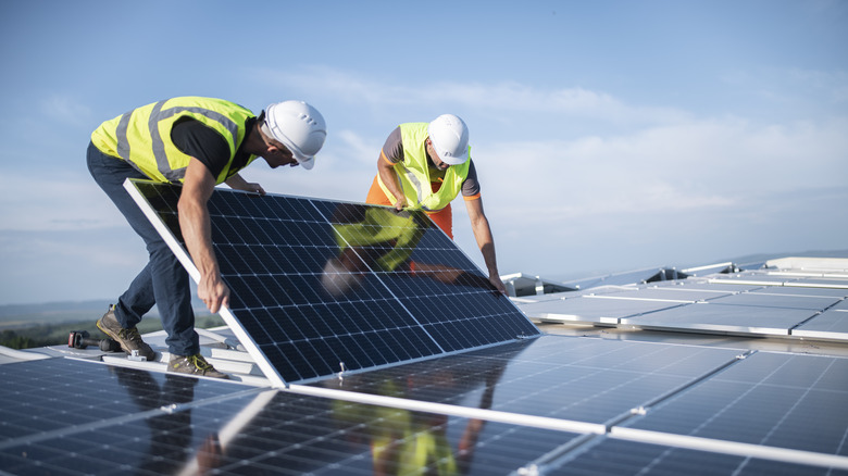
Installation and Construction Phase
Industry data indicates that over 35% of early performance degradation and corrosion issues are directly attributable to oversights during the installation phase. An improperly installed plant, even inland, faces a soaring risk of electrochemical corrosion on frames and internal circuits, potentially reducing the expected 25-year lifespan by a direct 20% discount, and requiring expensive repairs within 5-8 years.
Hardware Compatibility
Over 35% of early corrosion failures in the industry stem from hardware Matching and installation techniques. A startling statistic: in coastal areas, the mistake of using ordinary carbon steel bolts to secure aluminum frames can increase the frame's corrosion rate by over 5 times within 3 years, reducing structural strength and causing an annual system generation loss of nearly 2%. Investment in this area accounts for only 1.5%-2% of the total plant cost, but if errors occur, the repair cost can be 10-20 times the initial savings.
1. Metal Clash: How Galvanic Corrosion Can Bite You Hard
· The Principle is Critical: When you bring aluminum alloy frames together with ordinary carbon steel support or bolts, and there's just over 60% relative humidity in the air forming an invisible water film, they instantly form a "micro-cell." Aluminum, being more chemically active, acts as the anode and is "sacrificed," continuously losing electrons and turning into white corrosion powder. Lab accelerated corrosion tests show that at 3.5% salt spray, the corrosion depth at incompatible metal contact points can be 8-10 times that of normal conditions.
The Solution Must Be Rigorous:
· Bolt and support Material: A2-70 (304) grade stainless steel must be used, and A4-316 grade stainless steel is preferred. For a 10kW system, using all qualified stainless steel fasteners costs about 400-600 RMB, only 200-300 RMB more than ordinary carbon steel parts, but it completely eliminates this risk. The use of galvanized (white zinc, yellow zinc) bolts is absolutely prohibited, as the zinc coating typically fails within 18 months outdoors, wearing off to expose the carbon steel core, leading to worse consequences.
· Physical Isolation is Double Insurance: Even after using stainless steel bolts, it is highly recommended to install neoprene or EPDM washers at least 1.5mm thick between the bolt and the aluminum frame, and between the support and the frame. This washer not only prevents hard contact from scratching the oxide layer but also effectively blocks the flow of electrolyte (rainwater, moisture) between the two metals, reducing the probability of corrosion by over 90%. The cost of washers is extremely low, less than 0.5 RMB each.
2. Clamps: How Tight is "Just Right"?
· Consequences of Under-Tightening (<14 N·m): When wind speed reaches 22 m/s (about Beaufort 9), the module may experience continuous micro-motion friction against the support, slowly wearing away the 5-10 micron thick anodized layer on the frame surface like sandpaper. Friction point temperature can instantly exceed 70°C, accelerating corrosion.
· Torque is Not Mysterious: Clamps shouldn't be tightened as much as possible. Each major module manufacturer specifies a torque range for the bolts in the installation manual, typically between 16-20 N·m (Newton-meters). You must use a calibrated torque wrench for installation, not by feel.
· Clamp Selection Itself: Prioritize clamps with a larger contact area with the module frame and anti-slip ribs/serrations. This distributes pressure more evenly, avoiding stress concentration. Increasing the contact area from a conventional 15 cm² to 25 cm² can reduce the pressure on the oxide layer by about 40%.
3. Mounting Rails: The Overlooked Source of Corrosion
· Material and Thickness: Rails are commonly carbon steel, but the anti-corrosion coating is key. Hot-dip galvanizing is the industry standard, but you must pay attention to the zinc coating thickness. For outdoor use, the minimum local zinc thickness should not be less than 55μm, and the average thickness should reach 70μm or more. Inferior products with coatings of only 20-30μm may see the zinc layer consumed in 3-5 years in a moderately corrosive environment, starting to rust.
· Treatment of Cut Ends: This is the most easily neglected weak point. When you cut rails on site, the exposed carbon steel cut ends must be treated for corrosion protection. The standard practice is to apply a zinc-rich primer (zinc content not less than 80%), with a coating thickness of at least 100μm, ensuring its corrosion resistance matches the galvanized layer. An untreated cut end will start rusting there, extending inward by 5-10 cm within 2 years, seriously affecting structural safety.
4. Grounding: Good Intentions, Bad Outcomes
· The Most Critical Mistake is to use bare copper wire directly wrapped or crimped onto the aluminum frame for grounding. The electrode potential difference between copper and aluminum is as high as 0.6 volts, far exceeding the 0.3 volts between aluminum and steel. This combination leads to extremely rapid corrosion in humid environments, potentially causing severe corrosion perforation of the frame within 12 months.
· The Correct Approach is to use dedicated PV grounding clips. These clips are typically made of stainless steel or tinned copper, compatible with aluminum frames; their internal stainless steel teeth penetrate the oxide layer for a reliable electrical connection; they have an external protective cover and are connected to the grounding electrode via a yellow-green grounding cable with a cross-section not less than 6mm².
Mechanical Damage Protection
Field data indicates that approximately 15% of early module failures (within the first 3 years of operation) can be attributed to physical damage during the installation phase. The back sheet of a standard 72-cell polycrystalline module has an average thickness of only 0.35 mm, equivalent to the thickness of three or four stacked A4 papers.
The compressive stress layer of the glass is also only in the range of 20-30 MPa. An inadvertent drag, a dropped tool, or an installer mistakenly stepping on a module can generate localized pressure sufficient to exceed the protective limits of these materials, causing irreversible damage.
These "minor injuries" not only affect appearance but also open direct channels for moisture and salt spray to corrode internal cells and bus-bars, causing the power degradation rate to skyrocket from the normal 0.5-0.8% per year to 3-5%, or even induce hot spots, rendering over 30% of the cell string ineffective.
1. Handling and Placement: Don't Let Modules Get "Disfigured"
· Manpower and Gripping Points: Moving a module nearly 2 sqm in area and weighing over 25 kg should never be done by one person. It requires coordination by at least two workers, gripping the module firmly on the uncut original long frames on both sides. Strictly prohibit gripping the short edges with one hand or hooking fingers into the junction box area on the back sheet.
· Ground Placement "Cushioning": Modules must never be placed directly on the ground, gravel, or uneven support. When placing, use at least 3 wooden blocks of consistent height, with a width not less than 10 cm and thickness not less than 5 cm.
2. Tool Management: Your Wrench Could Be a "Weapon"
· Tool Carrying Specifications: The tips of metal tools like screwdrivers, wrenches, and pliers in an installer's tool belt have a hardness (typically HRC hardness over 50) much higher than glass and back sheets.
· Installation Platform Management: When modules are laid out but not fully secured, strictly prohibit placing any tools, bolts,support parts, or other metal objects directly on the module surface. On one hand, these items can scratch the glass; more importantly, a stainless steel nut weighing only 100 grams can easily reach a surface temperature exceeding 80°C under the sun, creating a local hot spot with a temperature difference over 40°C from the surrounding cooler areas.
3. Installation Operations: Force and Angle Matter
· Aligning Holes, Avoid Prying: When fitting the module into the rail clamps, if the holes are slightly misaligned, never use a screwdriver or other tool to forcibly pry the frame into alignment.The correct method is to slightly adjust the position of the clamps on the rail, leaving 1-2 mm of adjustment tolerance.
· Cable Bending Radius: The DC cables coming from the junction box typically have copper conductor cross-sections of 4mm² or 6mm². During installation, ensure they bend naturally, with a minimum bending radius not less than 5 times the cable diameter (typically needs to be greater than 50 mm).
4. Stepping Taboos: Modules Are Not Scaffolding
· Absolutely prohibit walking on installed modules. The tempered glass can withstand uniform snow loads (often up to 5400 Pa, equivalent to nearly 1 meter of snow) and wind pressure, but cannot withstand the enormous pressure from a point load like a shoe sole (e.g., a heel, contact area maybe only 5 cm²). An installer weighing 75 kg stepping on it can generate instantaneous pressure exceeding 15 MPa, far exceeding the glass's designed compressive strength, almost certainly causing "cobweb" cracks inside the glass and shattering many underlying cells, immediately rendering the module useless.
· If system maintenance truly requires personnel to work within the array, dedicated maintenance walkways/boards must be planned and installed beforehand, distributing the person's weight across multiple modules and support. When temporary contact with the module surface is necessary for operations like wiring, use planks over 30 cm wide and 1 meter long, or specialized tread pads for support, ensuring the contact area is large enough to distribute the pressure to a safe range.
Electrical Connections and Sealing
Industry tracking data shows that nearly 28% of plant failures (e.g., PID, leakage, short circuits) are directly related to sealing failure. If a junction box's waterproof gland is not installed properly, the resulting trace amount seepage might show no signs for 1-2 rainy seasons, but will keep internal humidity consistently above 85% RH, corroding metal pins and PCBs at 5-10 times the normal rate, eventually leading to increased connection resistance, heating, or even arcing.
Risk Point | Potential Consequence | Probability of Occurrence | Repair Difficulty & Cost (Estimate) |
Junction Box Cable Outlet | Internal corrosion, leakage current, PID effect | High | Medium-High, requires junction box replacement, ~200-500 RMB/each |
MC4 Connector Mating | Increased contact resistance, arcing, burnout | Medium | Medium, requires re-termination, ~50-100 RMB/pair |
Module Frame Sealant | Moisture ingress causing internal cell corrosion | Low (but fatal) | Extremely High, module essentially scrapped |
Rail Grounding Connection Point | Grounding failure, safety hazard | Medium | Low, but requires periodic inspection |
1. Junction Box: How Tight is "Leak-Proof"?
· The "Critical Point" of Waterproof Glands: Most junction box cable outlets use metric threads (e.g., M20×1.5) with waterproof glands. Sealing relies entirely on the elastic deformation of the internal rubber seal under compression. Hand-tightening typically achieves only 0.5-1 N·m torque, far below the effective compression range of the seal. Standard operation requires using a tool to apply the manufacturer's recommended torque of 2.0 - 2.5 N·m. At this torque, the seal compresses about 25%-30%, perfectly filling microscopic gaps between the cable and the gland nut. A simple, practical field check: after tightening, the metal gland nut should not be easily turned by hand.
· "Millimeter-Level" Precision of Cable Stripping Length: The length of insulation stripped from cables entering the junction box must be precisely controlled. Too long (e.g., over 15 mm), the exposed copper strands might contact other live parts inside the box under pulling force, causing a short circuit. Too short (e.g., less than 8 mm), might result in insufficient contact area with diode pins or terminals, increasing contact resistance, creating a potential hot spot. The optimal length should strictly follow the junction box's internal marking, typically between 10-12 mm.
2. MC4 Connectors: It Only Counts When You Hear the "Click"
· Mating Force and Sound: An incompletely mated connector can have contact resistance 10 times higher than normal (typically less than 0.5 milliohms). When carrying 8-10A operating current, that point will continuously heat up, potentially 30-40°C above ambient, accelerating plastic aging and eventual melting.
· Heat Shrink Tubing is the Second Lifeline: In harsh outdoor environments (especially salt spray, high humidity), a length (≥80mm) of dual-wall adhesive-lined heat shrink tubing (diameter Φ8-10mm) must be applied over the tail of each mated MC4 connector pair. Use a heat gun to shrink it evenly. The sealant at both ends will melt and adhere firmly to the cable jacket and connector tail, forming a secondary IP68 level protection. This measure, costing only 2-3 RMB, can reduce failure rates at connections by another 70%.
3. Frames and Back sheets: Inspecting Those "Inherent" Weak Points
· Seal Check at Frame Corner Joints: Aluminum frames of polycrystalline modules are typically mechanically riveted or glued at the four corners. Before installation, carefully inspect the seams at all four corners with a flashlight for obvious uneven sealant filling, bubbles, or cracks.
· "Tolerance" for Back sheet Scratches: Minor scratches during installation are hard to avoid. A surface scratch less than half the total back sheet thickness deep (approx. 0.15mm) and shorter than 2cm is generally acceptable. But any scratch exposing the back sheet substrate (typically PET or PP), especially if the internal white encapsulate (EVA) is visible, must be immediately repaired using a dedicated weather-resistant silicone sealant (e.g., MS Polymer). The application area should extend 1 cm beyond the damage edges and ensure complete coverage.
4. Cable Entry Holes and Conduits: Details Determine Success
· "Watertight Method" for Roof Penetrations: When cables pass through metal roof tiles or concrete roofs, the hole diameter should be only 4-6 mm larger than the cable bundle diameter. After pulling cables, use properly sized metal or plastic waterproof cable glands on both sides of the hole. On tiled roofs, additionally cover with a weather-resistant plastic waterproof flashing to create a drip edge. Absolutely avoid filling directly with foam or ordinary silicone; these materials have poor aging resistance and will crack or powder within 2-3 years.
· "Slack" in Cable Tying: When securing DC cables in conduits or on support, don't tie them too tightly. Plastic zip ties should have about a finger's width (1.5 cm) of slack. Over-tightening acts like a blade, continuously cutting the cable's outer insulation under daily temperature cycles (cables expand/contract up to 2%-3% in length), potentially causing the outer layer to crack within 3-5 years, compromising the inner insulation. Using dedicated UV-resistant cable clips providing more flexible support is recommended.
Active Protection Measures
Data shows that in highly corrosive environments, the power degradation rate of ordinary PV modules can be 1.5 times or more faster than in normal environments. Frames may develop severe white rust by years 8-10, threatening structural safety. Passively waiting for corrosion to occur before handling leads to high repair costs; a large-scale support replacement can cost 15%-20% of the initial investment.
The core idea of active protection is to invest a small budget (about 3%-5% of total system cost) during the construction phase or the early stages of corrosion. Through two core methods – material upgrade and surface enhancement – the system's corrosion resistance is elevated by an order of magnitude, ensuring the stability of power generation revenue over the future 25 years.
Special Protective Coatings
In coastal plants, the salt-laden air often maintains humidity above 80% RH, with chloride ion concentrations potentially exceeding 0.3 mg/m³. In such environments, the 5-10 micron oxide layer on ordinarily anodized aluminum frames can be breached within 3-5 years, starting pitting corrosion.
Once corrosion begins, the frame's mechanical strength degrades at 1%-3% per year, not only reducing power output but also creating structural safety hazards.
How to Choose Coatings? Understanding the Formulation is Key
Fluorocarbon Paint (FEVE): Top-tier, Specializes Against Salt Spray
Fluorocarbon paint's leading position comes from the carbon-fluorine bond in its molecular chain, one of the strongest chemical bonds in organic chemistry (bond energy up to 485 kJ/mol), making it super stable. Top-grade fluorocarbon topcoats can have a fluorine content (by resin solids) exceeding 22%, which is the core indicator of their super-long weather ability. In labs, a complete fluorocarbon system (80μm epoxy zinc-rich primer + 40μm fluorocarbon topcoat) passing 4000 hours of neutral salt spray test is just the baseline, equivalent to simulating 15 years of exposure in a harsh marine environment like Wanning, Hainan. The finished application price per square meter (including material, surface prep, labor) is about 55-75 RMB, but it can save you at least 2-3 large-scale maintenance cycles over the plant's life.
Epoxy Zinc + Polyurethane: The Economical and Practical "Heavy Armor"
This is the most classic, widely used heavy-duty corrosion protection combination. Its core advantages are excellent barrier properties and cathodic protection. The zinc content in the primer is crucial; high-zinc primers must have a zinc content by weight of 80% or more. Zinc has a more negative electrode potential than iron, so it corrodes preferentially, acting like a sacrificial anode to protect the underlying steel. This process can last 5-8 years. The topcoat uses a more weather-resistant aliphatic polyurethane, which can maintain more than 50% gloss (60° gloss) even after 5 years of outdoor exposure. The total cost of this system is about 60%-70% of the fluorocarbon system, around 35-50 RMB per square meter, making it a cost-effective choice for inland industrial and heavily polluted areas.
Polysiloxane Coatings: A New High-Performance Option
This is a newer technology with a solids content nearly 100% and very low VOC emissions, making it more environmentally friendly. Its biggest advantage is that a single coat can achieve high film thickness (150-250μm), whereas traditional systems require 2-3 coats. It has excellent heat resistance, with long-term temperature resistance up to 150°C, advantageous for module back surfaces that might experience hot spots. The drawback is the material itself is more expensive, 15%-20% higher than fluorocarbon paint, but the improvement in application efficiency can partially offset the cost.
Poor Application Renders the Best Coating Useless
Surface Preparation is the Lifeline: No Rust Removal Means Painting for Nothing
For any coating to adhere firmly, the substrate must achieve a cleanliness of Sa 2.5 grade. The abrasive used for blasting (e.g., copper slag, aluminum oxide) should be controlled to a particle size of 0.8-1.2mm to achieve an ideal roughness profile of 40-70 micrometers, providing strong "mechanical keying" for the coating. The prepared surface must receive the first coat of primer within 4 hours (shorter in high humidity, e.g., 2 hours), otherwise, the metal surface re-oxidizes.
Environmental Control is the Bottom Line: Temperature and Humidity Determine the Coating's Fate
During application, ambient temperature should be strictly controlled between 5°C and 35°C. The substrate surface temperature must be at least 3°C above the dew point; otherwise, moisture will condense under the film, causing blistering and layering later. Relative humidity must be below 85%. Spraying outdoors in high wind (wind speed over 4 meters per second) causes solvent evaporation too fast, leading to defects like dry spray and orange peel.
Film Thickness Inspection is Insurance: Rely on Data, Not Guessing by Eye
Coating thickness must be measured using a magnetic or eddy current gauge in a "grid pattern." For a single support member, measure at least 5 points per square meter. The final acceptance criteria are: 85% of measurement points should not be below the design thickness (e.g., 200μm), and the remaining 15% should not be below 85% of the design thickness (i.e., 170μm). No single point should exceed twice the design thickness, as excessive thickness increases internal stress and risk of cracking.
Material Upgrade
In strong salt spray areas less than 1 km from the coast (C5-M environment), even hot-dip galvanized steel support with standard thickness (≥60μm) may show red rust as early as 6-8 years.
Over the plant's 25-year operational cycle, at least 2 comprehensive support anti-corrosion overhauls would be needed. The cost of each, amortized per watt, is about 0.05-0.08 RMB. For a 50MW plant, this amounts to an additional expenditure of 2.5 to 4 million RMB.
The logic behind material upgrade is to convert these future, uncertain, recurring maintenance costs and downtime generation losses (about 2%-3% of annual revenue) into a one-time, certain initial investment increment during construction.
Stainless Steel: The Ultimate Choice for Top-Tier Corrosion Battlefields
304 or 316? Molybdenum is the Dividing Line
l 304 Stainless Steel (06Cr19Ni10): Contains about 18% chromium, 9% nickel. It handles C3 (urban) and most C4 (industrial) environments easily. But its tolerance limit is low in chloride-containing coastal or chemical plant areas. Risk of pitting increases significantly when chloride concentration exceeds 200ppm.
l 316 Stainless Steel (06Cr17Ni12Mo2): The key addition compared to 304 is 2%-3% Molybdenum (Mo). Molybdenum greatly enhances resistance to pitting and crevice corrosion. Its resistance to chloride-induced corrosion is over 3 times that of 304. Within 500 meters of the coast or anywhere you can smell the sea, 316 is the starting choice. Price-wise, 316 profiles are about 15%-20% more expensive than 304, and about 150%-200% more expensive than ordinary hot-dip galvanized steel.
Surface Finish Also Matters
Recommend using 2B finish (cold-rolled, bright annealed) or mechanically polished surfaces. Smooth surfaces reduce the area for pollutants and moisture to adhere, allowing the passive film to form more completely and repair itself faster.
Hot-Dip Galvanized Steel: The King of Cost-Effective in Inland Environments
Coating Thickness is the Decisive Factor for Lifespan
Never just accept "hot-dip galvanized"; you must specify the coating thickness. According to ISO 1461, for steel thicknesses commonly used in support(3-6mm), the minimum local coating thickness should be 70μm, and the average thickness should be 85μm. In C4 (high corrosivity industrial/coastal) environments, increasing the coating thickness by 25μm roughly extends the anti-red-rust life by 3-5 years. Some quality suppliers offer "heavy-duty" options with average thickness ≥100μm, which, while costing 10%-15% more, is often worth it.
Coating Quality is More Critical Than Thickness
The coating isn't a simple layer of zinc but a metallurgically bonded, layered structure. High-quality galvanizing should show a bright, uniform "spangle" pattern, free of bare spots or dross. Adhesion must pass a cross-cut test achieving the highest grade (ISO 0). Inferior galvanizing has a brittle, flaky layer that peels off easily, drastically reducing lifespan. During installation, cut and welded areas must be rigorously repaired using a zinc-rich primer + epoxy mica iron oxide intermediate coat + polyurethane topcoat system, with a total dry film thickness ≥200μm. This is the most commonly overlooked weak point.
Composite Materials and Aluminum Alloy: Lightweight Solutions for Specific Scenarios
Composite Material Frames: Completely Insulated and Corrosion-Free
Frames made primarily of materials like glass fiber and epoxy resin have the major advantage of being completely insulating and having zero corrosion. Their density is about 1.8-2.0 g/cm³, about 25% lighter than aluminum alloy (~2.7 g/cm³), reducing the module's overall weight. Tensile strength can exceed 500 MPa, comparable to high-quality aluminum. The current main obstacle is cost, about 20%-30% higher than ordinary aluminum frames, and connection designs often use adhesive bonding + mechanical fastening, requiring high process precision.
Aluminum Alloy Mounting Systems: Balancing Lightweight and Corrosion Resistance
6005-T6 series aluminum alloy support have inherent atmospheric corrosion resistance superior to steel, often requiring no additional coating in C3/C4 environments. Low density makes installation convenient. To achieve the same load-bearing capacity as steel support, the profile cross-section usually needs to be larger, using more material, resulting in costs about 80%-120% higher than hot-dip galvanized steel.
Doing the Full Accounting: Why Higher Initial Investment Can Be Cheaper?
The decision to upgrade materials cannot be based on purchase price alone; a 25-year Life Cycle Cost (LCC) analysis must be performed.
Take a support system for a C5-M highly corrosive environment as an example:
· Option A (Hot-Dip Galvanized Steel): Initial cost set at 100%. Expect the first comprehensive anti-corrosion maintenance around year 8, costing about 35% of initial investment; second maintenance around year 16, costing about 40% (due to more complex disassembly). 25-year total cost ≈ 100% + 35% + 40% = 175%. This doesn't include the generation loss from plant downtime during the two maintenance periods.
· Option B (316 Stainless Steel): Initial cost is 250%. Over 25 years, apart from routine inspection, there are no large-scale anti-corrosion maintenance expenditures. 25-year total cost ≈ 250%.