How to Install a Portable Solar Module and a Small Solar Module
Install portable panels by securing with rubber pads (10cm² base) to prevent slips, then link via MC4 cables, checking polarity. For small modules, mount on aluminum frames (3mm screws), seal edges with silicone, and test output with a multimeter (target 18V DC).
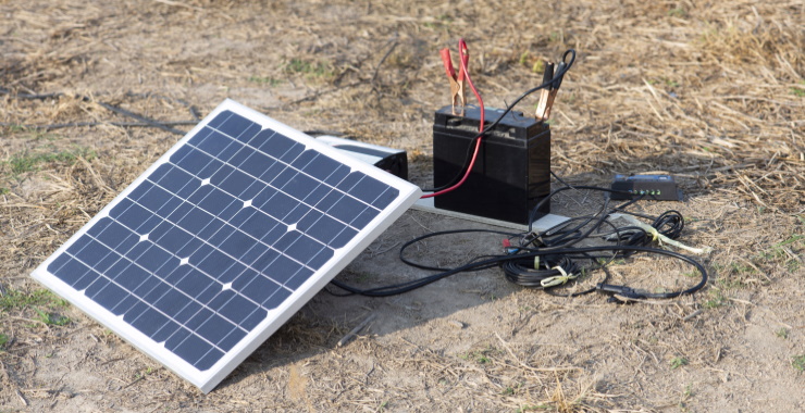
Portable Solar Panel Installation
A 100W portable solar panel can fully charge a 24,000mAh power station in just 3 hours, at a cost only 1/5 that of a disposable power bank.
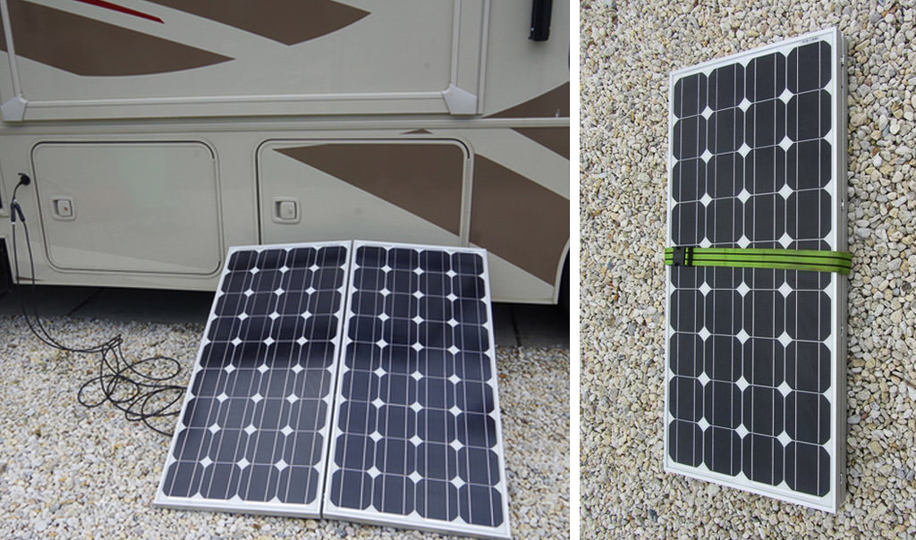
With monocrystalline silicon cell conversion efficiency now exceeding 23.5%, a foldable solar panel the size of an A3 sheet and weighing only 2.5kg when folded can deliver a peak power of 160W when unfolded, sufficient to power a laptop (65W) and a drone cell (30W) simultaneously.
However, 90% of users experience over 20% loss in actual power generation due to installation oversights.
Mathematical Relationship Between Mounting Angle and Light Efficiency
Taking a nominally 100W panel as an example, if laid flat in central Beijing (39.9°N latitude), its average daily power generation in spring and autumn is only 0.45 kWh. However, by precisely adjusting its tilt angle to 40°, the daily generation under the same light conditions jumps to 0.61 kWh, an increase of over 35%.
First, Understand the Principle: Why Can a 10° Angle Difference Cause a 20% Power Difference?
Sunlight hits solar panels in two forms: direct and diffuse. When the light rays are perpendicular to the panel surface, the energy received per unit area is the strongest, resulting in the highest power generation efficiency. This relationship can be quantified with a simple trigonometric function: Effective Light Intensity = Sunlight Intensity × sin(Solar Altitude Angle + Panel Tilt Angle). For example, assume the solar altitude angle at noon on a summer day is 70°. If your panel is laid flat (0° tilt), then sin(70°) ≈ 0.94. If you adjust the panel to 20°, then sin(90°)=1, meaning the theoretically received energy differs by 6%. And this is just at noon. If you factor in the oblique sunlight in the morning and afternoon, the energy loss due to angle mismatch can quickly amplify to over 20%.
A Universal Formula: Find the "Golden Angle" for Your Location
The most practical rule of thumb is: "Use latitude for Spring and Autumn Equinox, subtract fifteen for Summer Solstice, add fifteen for Winter Solstice."
l Latitude Baseline: The latitude of your area is the most important reference value. For example, if you are in Shanghai (31°N), the optimal tilt angle in spring and autumn is around 31 degrees.
l Seasonal Fine-Tuning:
l Summer: The solar altitude angle is high, so the tilt angle should be reduced. The formula is [Local Latitude - 15°]. The summer angle for Shanghai is about 31° - 15° = 16°.
l Winter: The solar altitude angle is low, so the tilt angle should be increased. The formula is [Local Latitude + 15°]. The winter angle for Shanghai is about 31° + 15° = 46°.
l According to actual measurements, in the Shanghai area, adjusting a 100W panel from 31° to 16° in summer can stably increase the charging current by 12%-18% in the afternoon (2-4 PM), as it better captures the oblique afternoon sunlight.
Don't Be Lazy: The Benefits of Frequent Adjustments Far Exceed Your Imagination
While we don't need to adjust every day, making adjustments at key times yields significant benefits. It is recommended to follow the principle of "Major adjustments twice a season, minor adjustments monthly."
l Major Adjustments: Perform two significant angle changes per year: mid-April (spring to summer transition) and mid-October (autumn to winter transition).
l Minor Adjustments: Within each major adjustment period, spend one minute each month to fine-tune the angle by about 5 degrees based on the current month. For example, at 40°N latitude, you can gradually reduce the tilt angle from 40° to 25° from April to August. Data shows that this fine-tuning can generate 15% more electricity annually compared to a fixed angle.
No Protractor Handy? Use Your Smartphone.
1. Search for an "Inclinometer" or "Level" APP in your app store. The accuracy error of most free apps is within 0.5°.
2. Place the phone directly against the aluminum frame edge of the solar panel (ensure the frame is flat). The angle displayed on the app is the panel's tilt angle.
3. Advanced Technique: Some advanced apps can even use the camera and GPS, combined with the date and time, to directly calculate the optimal angle to face the sun at the current moment, achieving true "sun-tracking" placement.
Practical Data: See How Much Extra Power Precise Angling Can Charge
Let's look at a set of actual measurement data. Location: Guangzhou (23°N). Test panel: 120W portable foldable solar panel. Test subject: 2000Wh power station.
l Scenario A (Random Placement): Panel laid flat on grass. From 10 AM to 4 PM, total energy charged was about 580Wh.
l Scenario B (Precise Adjustment): According to the formula, the optimal angle for Guangzhou in June is 23° - 15° = 8°. During the same time period, the energy charged reached 782Wh.
l Result: An extra 202Wh of energy was charged. This is enough to fully charge a smartphone over 15 times, or run a car refrigerator for an extra 3 hours.
Exponential Losses from Shading and Obstruction
Actual measurement data shows that on a standard 100W solar panel using 36 monocrystalline silicon cells (each 156mm×156mm), if just 5% of the area of one cell (about 12 square cm, the size of a credit card) is shaded by a leaf, the entire panel's output power can drop from a peak of 98W to around 65W, an immediate loss of over 30%.
If this shadow happens to fall on the cell's main busbar, completely shading the entire cell, the power can plummet further to below 35W, an efficiency loss of up to 65%.
A shadow the size of a palm can, under specific conditions, paralyze a solar system of hundreds of watts. This is not linear attenuation, but exponential collapse.
The Fatal Flaw of Series Circuits: Current is Limited by the Unluckiest Team Member
Current portable solar panels, whether 100W or 200W, basically connect dozens of cells in series to increase voltage.
Each standard cell can produce about 0.5V voltage and 6-7A current under full sun. When all cells are intact, 36 cells in series produce about 18V, with a stable current around 6A (18V × 6A ≈ 108W). Once one cell is shaded, its resistance increases dramatically, turning from a "conductor" to a "resistor." The current of the entire circuit is immediately limited to the tiny current this shaded cell can produce, maybe only 1-2A.
Thus, the entire panel's output power becomes 18V × 2A = 36W. This is why shading a small area can be just as bad as shading a large area initially.
Bypass Diodes are Saviors, But Don't Rely on Them Entirely
To solve this problem, engineers install modules called "bypass diodes" in solar panels. Their role is like building an "emergency lane" next to each group of cells (typically 12 or 18 cells per group). When shading occurs within a group of cells, the diode automatically conducts, allowing current to bypass the "paralyzed" group and flow directly through the emergency lane. For example, a 36-cell panel is usually divided into 3 groups of 12 cells. If the shadow only affects one group, the diode bypasses that group, allowing the remaining 24 cells to continue working. The panel's output voltage drops from 18V to 12V, but the current can mostly be maintained. Theoretically, the output power becomes 12V × 6A = 72W, which is twice as good as the complete failure of 36W.
But diodes have limits. First, they themselves have a forward voltage drop of about 0.7V, causing additional losses. Second, if the shading is scattered, affecting parts of two groups, the situation becomes complex, and efficiency losses add up. Worst of all, low-quality panels may use diodes with insufficient capacity, which can burn out under prolonged high bypass current, causing the entire "emergency lane" to fail.
Which Shade is Most Deadly? Location is More Important than Area
l Horizontal Strip Shadows (e.g., a shadow from a pole spanning several cells): This is the most deadly type. It simultaneously reduces the current of the shaded cells in each group, causing multiple bypass diodes to activate, leading to a step-like drop in voltage and power.
l Point Shadows (e.g., bird droppings, a leaf): If it completely covers one cell, it disables that cell. But if it's small, covering only part of a cell, the impact is relatively isolated.
l Vertical Strip Shadows: If the shadow runs along the direction of the cell string, it might only affect one or two cells, making it easier for the bypass diode to intervene, and the impact is controllable.
l Actual Test Case: At 3 PM, a shadow from a 2cm diameter branch falls diagonally on a 100W panel. The shadow area might only be 30 sq cm. But when it spans a critical connection point between three cell groups, the panel output instantly drops from 85W to 28W. Bird droppings of the same area, while unsightly, only cause a 10W power drop.
Shading Traps in Daily Use: The Loss Culprits You Don't Even Notice
1. Shadow from the Panel Frame: In the early morning and late evening, when the sun angle is low, even the panel's own aluminum frame can cast a significant shadow on the cells. A 5cm wide frame, when the solar altitude angle is below 30 degrees, can cast a shadow covering an entire row of cells, reducing charging efficiency by over 50% in the early morning and dusk.
2. Uniform Shading from Dust Accumulation: A thin layer of dust is equivalent to putting a uniform "shadow" over every cell. Data shows that a panel left uncleaned for a week has an average power generation efficiency 8%-15% lower than a clean panel.
3. Rapid Changes from Clouds: The flickering light from passing clouds causes the solar panel's output power to fluctuate violently between 30% and 100%.
Millimeter-Level Game of Line Loss Control
A 3-meter long, nominally 2.5 sq mm high-quality copper cable, when transmitting 6A current, has a voltage drop of about 0.36V. For an 18V, 100W solar panel, the power loss is about 12W (18V × 6A = 108W theoretical, actual output is (18V - 0.36V) × 6A ≈ 105.8W, line loss about 2%).
But if inferior copper-clad aluminum wire is used, or the cable is extended to 5 meters, the surge in resistance could cause a voltage drop exceeding 1.5V. The output power would then plummet to (18V - 1.5V) × 6A = 99W. The line loss itself consumes nearly 9W of power, equivalent to an immediate 10% discount on the panel's efficiency.
How Does Line Loss Steal Your Electricity? It's Basically Resistance Causing Trouble.
Current flowing through a wire encounters resistance. This resistance consumes electrical energy, converting it into heat. This loss follows a physical formula: Power Loss = Current squared × Resistance (P = I² × R).
l Charging a phone (current ~1A), line loss is almost negligible.
l Charging a 60W laptop (current ~3.3A), line loss starts to become noticeable.
l If powering a laptop and a small fridge simultaneously (total current reaches 8A), line loss becomes very severe.
Therefore, in high-current application scenarios, the requirements for cable specifications increase exponentially.
The Three Elements of Cables: Thickness, Length, Material – None Can Be Compromised
1. Wire Gauge (Thickness) is Decisive: The cross-sectional area of the wire (in square millimeters, mm²) directly determines the resistance. Larger area means lower resistance. For 12V/24V solar systems, follow this basic principle:
l Current below 10A, length under 5 meters, use at least 2.5 mm² wire.
l Current 10A-20A, must use 4 mm² wire.
l Current over 20A, consider 6 mm² or thicker wire.
2. An inferior wire with an actual core diameter less than 2.0 mm² may have a resistance over 50% higher than a standard 2.5 mm² wire
3. Length is a Silent Killer: The longer the cable, the greater the total resistance. Loss is proportional to length. The solution is simple: Use a 3-meter cable if it meets the need, never use a 5-meter cable unnecessarily. If extension is necessary, prioritize increasing the wire gauge rather than reluctantly using a thin, long cable.
4. Material is Key to Price and Performance: Be sure to use pure copper (T2 red copper) wire. Many cheap wires on the market are copper-clad aluminum, meaning the core is aluminum with a thin layer of copper plating. Aluminum's resistivity is about 60% higher than copper's.
Don't Underestimate Connectors; They are a Major Loss Area
A poor-quality or oxidized connector can have a contact resistance equivalent to adding an extra half-meter to one meter of inferior wire. MC4 connectors are the standard in the solar industry. High-quality MC4 connectors use silver-plated or at least tin-plated copper cores with good elasticity, ensuring large contact area and low resistance. Inferior MC4 connectors might use an iron core with a thin copper plating, which rusts quickly, causing the connector resistance to soar from a few milliohms to hundreds of milliohms. A rough way to judge connector quality: after transmitting a relatively high current (e.g., over 5A) for 10 minutes, touch the connector temperature with your hand. If it's noticeably hot to the touch, the contact resistance of this connector is too high and is wasting your electricity.
Small Solar Panel System Installation
A 300-watt monocrystalline panel measures about 1.7 meters long and 1 meter wide, weighing around 20 kilograms. On a sunny day, it can generate about 1.2 kWh of electricity (based on 4 hours of peak sun). The lights, router, and security camera on your balcony might use a total of about 0.5 kWh per day.
Thus, the electricity generated by this panel is not only sufficient but leaves an extra 0.7 kWh to store. At 0.6 RMB per kWh, that saves 0.3 RMB per day, or over 100 RMB per year. The initial investment for a basic system (panel + controller + cell + mounting) is about 1500 RMB, with a payback period of roughly 10-12 years. Since the panel lifespan is over 25 years, the following decade or more is pure profit.
Core Module Selection
A 300W system can cost anywhere from 800 RMB to 2000 RMB. The price difference of 1200 RMB is hidden in the parameter details of modules like the panel, controller, and cell. Choosing correctly can result in a difference of over 20% in power generation over the next 10 years, equivalent to earning several free panels. For example, an MPPT controller costs about 150 RMB more than a PWM controller, but it can squeeze out 30% more electricity on cloudy days, generating an extra 30 kWh per year, paying for itself in about two years. Below, we break down how to evaluate the parameters of each module to spend your money wisely.
1. How to Choose a Solar Panel? Monocrystalline and Polycrystalline are Not the Same.
A monocrystalline panel rated at 22% efficiency compared to an 18% efficient polycrystalline panel: on the same 1.6 sq m area, the monocrystalline panel's nominal power can often reach 300W, while the polycrystalline might only be 280W. This means that for a fixed balcony area, installing monocrystalline panels can generate about 20 kWh more per year.
A panel rated at 18V Vmp might actually reach over 20V at summer noon. If you are using a 12V system, you must pair it with an MPPT controller to efficiently step down the high voltage for charging. If you use a cheap PWM controller, the voltage difference is directly wasted as heat, potentially causing a 30% generation loss.
2. Controller: MPPT and PWM – The Difference is More Than Just a Name
Simply put, a PWM controller acts like a switch, forcibly "pulling down" the solar panel's high voltage to the cell voltage for charging, wasting all excess power in between. An MPPT controller, however, acts like a smart transformer, continuously tracking the panel's optimal power point (e.g., 35V) and efficiently converting it to the voltage the cell needs (e.g., 14.4V) for charging.
Data shows that when your system voltage is 12V and the panel operating voltage is in the 18V-40V range, MPPT has the greatest efficiency advantage, typically 20%-30% higher than PWM. Especially during weak morning/evening light when the panel voltage is unstable, MPPT can continue charging, while PWM may have stopped working. A 30A MPPT controller costs around 300 RMB, about 150 RMB more than a PWM controller. But for systems over 300W, this investment can be recouped through the extra electricity generated within a year or two.
3. Cell: Cycle Life Directly Determines How Long Until Replacement
Ordinary car starting batteries die after a few deep discharges, while solar-specific deep-cycle batteries are designed for repeated charging. But even among "deep-cycle" batteries, the difference is huge.
Cheap lead-acid gel batteries have a nominal cycle life of about 500 cycles (at 50% Depth of Discharge). If you use half the capacity daily, the cell capacity will degrade to about 80% of its original capacity after roughly a year and a half. Lithium Iron Phosphate (LiFePO4) batteries, however, have a nominal cycle life of over 2000 cycles (at 80% DOD). With the same daily use, they can last over 5 years. Crunching the numbers: A 12V 100Ah lead-acid cell costs about 500 RMB. Over its lifespan, the total stored energy is about 500 cycles * 0.6 kWh/cycle = 300 kWh. The "equipment cost" per kWh is 1.67 RMB. A LiFePO4 cell of the same capacity costs about 1200 RMB. Over its lifespan, the total stored energy is 2000 cycles * 0.96 kWh/cycle = 1920 kWh. The equipment cost per kWh is only 0.625 RMB. In the long run, the actual cost of using LiFePO4 batteries is lower.
4. Mounting and Cables: Small Details Can Ruin a Large System
The aluminum alloy thickness for mounts should not be less than 1.5 mm, and stainless steel screws must be 304 grade. Inferior mounts may deform in a level 8 gale, increasing the panel's wind exposure area, potentially tearing the entire fixation point off the wall. During installation, each mount should have at least 4 M8×80 expansion bolts, with a drilling depth of over 60 mm.
DC cable losses are a silent killer of your electricity bill. If the distance from the panel to the controller exceeds 10 meters, using 2.5 sq mm cable instead of 4 sq mm cable can result in over 5% line loss. Simple calculation: At 10A current, 2.5 sq mm cable has about 0.007Ω resistance per meter. For a 20-meter round trip, the power loss is I²R = 100 * 0.28 = 28W. This is equivalent to 10% of a panel's generating capacity being directly wasted as heat in the wires. MC4 connectors must be firmly pushed together until they click. Poor contact causes continuous heating at the connector, potentially reaching temperatures over 70°C, accelerating aging and even causing fires.
Installation Practice
Many people think that buying all the modules is most of the battle, but the installation phase is actually where most accidents happen. A mistake in the connection sequence can destroy a 300 RMB MPPT controller in 0.1 seconds.
A solar panel's open-circuit voltage in sunlight is high. A panel rated at 18V can actually reach over 22V. Three in series would be 66V.
If this voltage directly hits a controller not connected to a cell, the instantaneous power overload can instantly burn out the internal MOSFETs. Data shows that over 70% of controller returns are due to incorrect installation sequences.
1. Gather Your Tools; Don't Go Looking for Them Mid-Installation
l Basic Electrician's Kit: Must include a digital multimeter with a voltage rating of at least CAT III 600V. A multimeter that can measure DC voltage and resistance is your "eyes" before and after installation.
2. Site Selection and Mounting – If It Can't Withstand Wind, It's All for Nothing
l Precisely Adjust Azimuth and Tilt with a Phone App: Don't guess. Download a "Solar Calculator" type app on your phone. Using the phone's sensors, you can read the current azimuth and tilt angles in real-time. In most parts of China, due south (azimuth 0 degrees) is the baseline. A deviation exceeding 15 degrees can result in an annual power loss of over 5%.
l Mounting Points Must be on Solid Walls: Absolutely banned fixed to insulation layers or hollow bricks. Use a hammer drill and M8×80mm metal expansion bolts. All 4 fixing points for each mount must be secure. The drilling depth should be over 60mm to ensure the expansion sleeve is fully opened. After installation, firmly shake the mount by hand to check if it's rock solid.
l Use Cushioning Pads Between Panel and Mount: Direct metal-to-glass contact, under high-frequency vibration caused by wind pressure, risks glass breakage.
3. Connection Sequence is an Iron Rule – One Wrong Step Costs Too Much
l Step One: Connect the Cell. This is the only correct way to "activate" the controller. Connect the cell cables (usually with pre-attached terminals) to the controller's "BATTERY" ports, strictly observing polarity (red positive, black negative). The controller screen should light up immediately, showing the cell voltage (e.g., 12.5V).
l Step Two: Connect the Load (if applicable). Connect the wires going to DC devices like lights or fans to the controller's "LOAD" terminals. You can set the load operating mode in the controller menu, e.g., automatically turning on lights at dusk.
l Step Three (The Last Step!): Connect the Solar Panel. After completing all the above connections and verifying they are correct, finally push the MC4 connectors from the solar panel together until they "click" firmly. At the moment of connection, watch the controller screen. It should immediately display the solar symbol and charging voltage (e.g., 18.5V), followed by the charging current.
4. Skipping Safety Measures is Like Burying a Landmine at Home
l A DC Circuit Breaker is Essential: You must connect a DC circuit breaker in series on the positive cell terminal before the controller. Its rated current should be slightly higher than the system's maximum current, e.g., use a 32A breaker for a system with a max current of 25A. This breaker is used for manually cutting power during maintenance and automatically trips in case of a short circuit, serving as the last line of defense.
l Re-test with a Multimeter: After all connections are made, use the multimeter's DC voltage setting to measure key points: Voltage across the cell should be around 12V; Voltage at the solar panel input should be the panel's open-circuit voltage (e.g., 22V); When charging, the cell voltage should slowly rise to 14.4V (absorption stage). Any abnormal voltage indicates a connection problem.
l Observe for Half an Hour After First Power-On: Don't leave immediately after connecting. For the first 30 minutes after the system is powered on, closely monitor the temperature of the controller and all cable terminals. Touch all metal connectors with your hand. Slightly warm is normal, but if it's hot to the touch (over 60°C), it indicates a potential high-contact-resistance issue that must be checked immediately after powering off.
Commissioning and Maintenance
An unverified system might be operating at 15% below standard efficiency, wasting dozens of kWh per year. Simple regular maintenance can not only keep the annual power degradation rate below 1% but also prevent premature equipment failure due to accumulated minor issues.
1. On First Power-Up, Watch the Controller Screen for Ten Minutes
l Charging Status Indicators: Most controllers display statuses like "Float," "Boost," "Equalize." When the cell is not full, the system should be in "Boost" mode, maintaining a higher charging voltage around 14.4V (for 12V systems) or 28.8V (for 24V systems), with current near the maximum under current light. If it shows "Float" (voltage ~13.6V) immediately, it might mean the cell is already full, or there's high impedance in the charging circuit.
l Real-time Power Comparison: Under clear weather, the instantaneous charging power (Voltage × Current) displayed on the controller should reach over 85% of the panel's rated power. For example, for a 300W panel, seeing over 250W charging power at noon is normal. If it's consistently only 150W, check for shading, excessive panel dust, or poor connections.
l Observe Temperature Changes Over Half an Hour: Touch the controller's casing and all cable connectors. They should feel warm, but should definitely not be hot to the touch. If a particular MC4 connector or terminal is noticeably hotter than others, it indicates high contact resistance, a long-term fire hazard. Power off and re-crimp or tighten the connection.
2. Set Controller Parameters; Don't Use Factory Defaults
l Cell Type Selection: In the system settings menu, precisely select the cell type: "Flooded," "AGM," "Gel," or "Lithium Iron Phosphate." The charge/discharge curves differ greatly. For example, mistakenly using "Flooded" mode for an LiFePO4 cell can cause overcharging, potentially reducing cell life from 2000 cycles to under 1000 cycles.
l Charging Voltage Fine-Tuning: If possible, refer to the cell manufacturer's technical manual to fine-tune the controller's "Boost/Absorption Voltage" and "Float Voltage." For instance, a specific LiFePO4 cell might recommend 14.2V absorption voltage, while the controller default might be 14.4V. This 0.2V difference significantly impacts cell health during long-term float charging.
l Load Operating Mode Setting: If DC loads (e.g., lights) are connected, set them to "Light On + Timer" mode. That is, turn on automatically at dusk and off automatically after a 4-hour delay. Avoid manual mode to prevent accidentally draining the cell, causing irreversible sulfation damage.
3. Create a Monthly Checklist – Eliminate Hazards in Five Minutes
Maintenance shouldn't wait for breakdowns; it should be regular preventive checks. Spend five minutes each month on the following:
l Power Generation Comparison: Record the monthly cumulative kWh generated from the controller and compare it with the previous month or the same period last year. If generation drops by more than 10% under similar light conditions, be alert.
l Surface Cleanliness Check: Wipe the panel surface with your finger. If you see obvious dust marks, it needs cleaning. Dust and bird droppings can reduce efficiency by 5%-15%. Rinse from top to bottom with a soft bristle brush and clean water. Never use abrasive scrapers or corrosive cleaners.
l Mechanical Structure Tightness Check: Shake the mounts and panels by hand to check for any signs of loosening in all screws and connectors. Perform this check especially after strong winds or heavy rain.
4. Adapt to Seasonal Changes – Different Strategies for Winter and Summer
l Summer – Prevent Overheating: For every 1°C increase in ambient temperature, a solar panel's output power decreases by about 0.4%. Ensure good ventilation under the panels to avoid heat buildup. Meanwhile, the controller and cell should be placed in a cool, ventilated area, with ambient temperature preferably not exceeding 45°C.
l Winter – Prevent Snow Accumulation and Low Charge: If winters are cold, consider increasing the panel tilt angle to help snow slide off. More importantly, keep the cell state of charge above 50% to prevent the electrolyte from freezing at low temperatures, which can crack the cell case.
5. Troubleshoot First – 80% of Problems are at the Connections
When you find the system not working or generation drastically reduced, troubleshoot in this order:
1. Check the Controller Display: Are there any error codes on the screen? Is there charging voltage but no charging current?
2. Measure Voltages: Use a multimeter to check if the solar panel's open-circuit voltage is normal (e.g., an 18V panel should read over 20V). Measure the cell voltage – is it above 11V (for a 12V system)? Below this, the controller might activate low-voltage disconnect protection.
3. Inspect Connectors: After powering off, unplug and replug all MC4 connectors and cell terminals. Focus on checking metal contacts for blackening, corrosion, or melting signs.