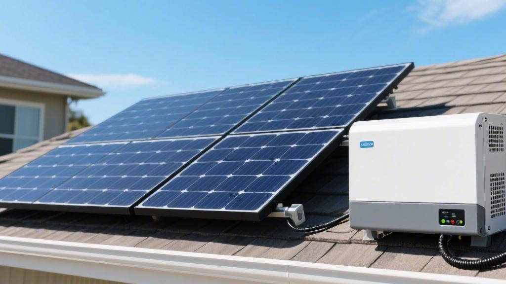
What is the difference between a solar panel and a solar inverter
Solar panels are responsible for converting light energy into DC power, with an efficiency of approximately 20%;
Inverters convert this into 220 V AC power, with an efficiency exceeding 98%.
During operation, DC cables must be used to connect the modules to the inverter interfaces, achieving the conversion from energy collection to household electricity.
Durability
The physical structure of solar panels is relatively simple, primarily composed of silicon wafers, tempered glass, EVA encapsulant, and a backsheet. With no moving parts, their power warranty is typically set between 25 and 30 years. In actual operation, the first-year degradation rate of high-quality monocrystalline silicon modules is usually controlled between 1% and 2%, followed by a linear annual degradation rate of approximately 0.4% to 0.55%.
By the end of the 25-year warranty period, the panels can still maintain around 80% to 84.8% of their initial rated power. In contrast, an inverter is a complex power conversion device integrating hundreds or thousands of electronic modules; its standard design life is usually between 10 and 15 years. Over a 25-year power station operation cycle, there is a near 100% probability that you will need to perform a full inverter replacement. This replacement cost typically accounts for 10% to 15% of the initial total system investment. For a 10 kW system, the budget for an inverter replacement after 10 years would be approximately 5,000 to 8,000 RMB.
Solar panels must be installed outdoors in direct sunlight, and their working temperature range is extremely wide, typically operating normally between -40°C and 85°C. However, panels have a negative temperature coefficient characteristic, with a power temperature coefficient usually between -0.3% and -0.39% per degree Celsius. When the panel temperature exceeds the Standard Test Condition (STC) of 25°C, every 1°C increase results in an output power drop of about 0.35%. Although high temperatures reduce instantaneous generation efficiency, they do not lead to rapid panel damage.
The endurance of an inverter is much more fragile. Its core internal modules—electrolytic capacitors—are extremely sensitive to temperature. According to the industry-recognized Arrhenius Law, for every 10°C increase in ambient temperature, the chemical life of a capacitor is halved.
If an inverter is installed in a poorly ventilated area or under direct sunlight where internal operating temperatures consistently exceed 60°C, its failure rate will be 3 to 5 times higher than if it were installed in a cool, ventilated place. This is why inverter housings usually feature large-area aluminum heat sinks or high-speed fans (with speeds typically between 3,000 and 5,000 RPM) to ensure the internal core temperature remains within the "golden zone" below 45°C.
When facing extreme weather such as hail, strong winds, or snow accumulation, panels face physical impact pressure, while inverters face electrical protection pressure.
· The front of a solar panel is typically covered with 3.2 mm thick ultra-white textured tempered glass, which can withstand the direct impact of a 25 mm diameter hailstone traveling at 23 meters per second. In load testing, standard modules can withstand a front static pressure of 5,400 Pa (equivalent to a snow load of 550 kg per square meter) and a rear wind pressure of 2,400 Pa.
· The defense priority of an inverter lies in its IP65 or IP66 protection rating. It can completely prevent dust ingress and withstand high-pressure water jets from any direction without damage. However, a more hidden threat to inverters comes from voltage fluctuations on the grid side.
· The most common loss for solar panels does not come from hardware damage but from "shading loss." According to experimental data, if just 5% of a panel's surface is covered by a layer of dust only 0.1 mm thick or bird droppings, its power generation efficiency can drop by 5% to 10%. In arid and dusty regions, the cumulative annual power generation loss can reach over 20% if quarterly cleaning is not performed.
The maintenance focus for inverters is on "health checks" rather than "cleaning." It is recommended to check DC wiring terminals every six months for signs of loosening or overheating discoloration. Since inverters often carry currents of 20A to 40A during full-load operation, poor contact at terminal posts can generate enough heat to melt plastic housings or even trigger a fire within minutes. Additionally, inverter firmware updates are crucial; optimization algorithms released by manufacturers can typically improve conversion efficiency by 0.1% to 0.3%, resulting in several thousand extra kilowatt-hours of revenue over a 25-year cycle.
Installation Location
The primary considerations for selecting a solar panel installation location are the azimuth and tilt angle, which directly determine the system's cumulative annual peak sun hours. In the Northern Hemisphere, True South (180° azimuth) is usually the ideal direction to obtain the maximum annual total radiation. If installation direction deviates 30° toward the east or west due to rooftop constraints, the annual power generation loss is typically between 3% and 5%; if the deviation reaches 60°, the loss expands to 10% to 15%. In addition to direction, the tilt angle should be as close to the local latitude as possible. For instance, in a region at 30° latitude, installing panels at a 30° tilt can increase annual power generation by about 10% compared to horizontal placement.
Shading Loss Data Reference:
If 5% of a 550W panel's area is shaded by a nearby utility pole or chimney, the overall output power of that array string may plummet by 30% to 50% due to the series circuit characteristics within the module. Therefore, when choosing a location, it must be ensured that the panel surface is free of any "hard shadows" during the golden generation hours from 9 AM to 3 PM.
A single panel typically measures approximately 2.27 meters in length and 1.13 meters in width, weighing around 28 kg. This requires the installation location's structural load capacity to reach at least 20 kg to 30 kg per square meter. When installing on flat roofs, inter-row spacing usually needs to be maintained at 2 to 3 meters to prevent front rows from shading the rear; the specific calculation formula depends on the sun's altitude angle at noon on the winter solstice. Furthermore, a ventilation gap of at least 10 cm to 15 cm must be left behind the panels. When the ambient temperature is 35°C, the lack of convection can cause the rear temperature of the panel to soar above 70°C, leading to a voltage output drop of about 12% for monocrystalline silicon cells.
The selection logic for an inverter's installation location is the opposite of that for panels; it is a precision electronic device that is afraid of heat, moisture, and needs a quiet environment. Although most mainstream inverters now have IP65 or IP66 protection ratings and can theoretically be installed outdoors, long-term UV exposure and high temperatures will accelerate the aging of plastic housing parts and the drying of internal electrolytic capacitors.
The ideal installation location is a cool, dry, and well-ventilated wall, such as inside a garage, in the shade under eaves, or in a dedicated equipment room. Data shows that when the ambient temperature around an inverter exceeds 40°C, the machine will automatically trigger rated power derating protection, with output power potentially restricted by 2% to 5% for every additional degree Celsius. If an inverter is forced to run at full load in a 50°C high-temperature environment, the failure rate of its internal IGBT power modules will be more than 10 times higher than at 25°C.
Installation Spacing Requirements Table:
Position | Recommended Clearance | Purpose |
Top | 50 cm or more | Ensures smooth upward discharge of hot air |
Bottom | 50 cm or more | Facilitates DC and AC cable wiring operations |
Left/Right Sides | 30 cm or more | Prevents heat accumulation when multiple inverters are side-by-side |
Additionally, inverters emit 40 to 60 decibels of electromagnetic interference noise or cooling fan sounds during operation, equivalent to the noise level of an old refrigerator or a small air conditioner. Therefore, it is strictly forbidden to install an inverter directly on the other side of a bedroom wall. The installation height is generally recommended to be around 1.5 meters above the ground, which prevents erosion from ground water accumulation and allows maintenance personnel to observe real-time voltage, current, and fault codes on the LED screen without a ladder.
The physical distance between panels and the inverter concerns not only construction difficulty but also the power conversion efficiency of the entire system. This stretch runs on Direct Current (DC), typically using 4mm² or 6mm² specialized photovoltaic copper core cables. When designing the installation location, the DC cable length should be minimized to keep line voltage drop within 1%.
Assuming a 10 kW system with a DC side voltage of 600 V and a current of 16 A: if the distance from the panels to the inverter is 30 meters, using a 4 mm² conductor results in a two-way loop resistance of about 0.27 ohms, creating a voltage drop of approximately 4.3 V and a power loss of about 70 W. If the distance is extended to 100 meters, the voltage drop will reach 14.4 V, and the loss will increase to around 230 W. Every year, you would lose about 300 to 500 kWh of electricity for nothing.
Cable Selection and Cost Details:
· DC Side: It is recommended to keep the distance within 20 meters to ensure MPPT accuracy is not interfered with by long-line resistance.
· AC Side: The distance from the inverter to the grid-tied distribution box is equally sensitive. The AC side usually uses a three-phase five-wire or single-phase three-wire cable, with the cross-sectional area selected based on the inverter's maximum output current.
According to electrical safety codes in many regions, photovoltaic systems must have a "Rapid Shutdown" function. If the installation location is too hidden or hard to reach, firefighters may not be able to immediately cut off the high-voltage DC power in the event of a fire.
On commercial or steep roofs, panel installation must reserve fire walkways at least 50 cm to 80 cm wide. This is not only for fire safety but also for semi-annual panel cleaning. If the roof is packed full just to squeeze in two extra panels, cleaning personnel will have no room to move, and dust accumulation on the panel surfaces will lead to a system generation degradation of over 15% after 3 years.
Inverter brackets must be fixed using expansion bolts that penetrate at least 6 cm to 8 cm into solid walls, as a 20 kW inverter can weigh 30 kg to 45 kg. If installing on lightweight partition walls or wooden structures, additional rear support steel plates must be added to prevent long-term vibration from loosening fasteners.
Selection Considerations
When selecting solar panels, the primary focus is the ratio of photoelectric conversion efficiency to module specifications. Currently, mainstream monocrystalline module efficiencies on the market are generally between 21.2% and 22.8%. If you choose N-type TOPCon cells, their efficiency is typically 1% to 1.5% higher than traditional P-type PERC cells. On the same 20-square-meter roof, you can install an additional 300 W to 500 W of capacity.
Single module rated power is now mostly concentrated in 450W, 550W, and 670W tiers. Large-format modules (such as 210mm wafers) have an area of about 2.8 square meters; although they offer higher power, their open-circuit voltage is usually between 40V and 50V, with operating currents as high as 15A to 18A. During selection, you must confirm that the mounting system can withstand loads exceeding 25 kg per square meter and that the cable specifications are at least 6 mm² specialized DC copper core wire to prevent line losses exceeding 2% caused by high currents.
Parameter Type | Excellent Indicator Range | Selection Impact Detail |
First-year Degradation | 1.0% - 1.5% | Determines the generation peak for the first 12 months |
Annual Linear Degradation | 0.4% - 0.5% | Ensures 84.8% of nominal power remains after 25 years |
Temp. Coefficient | -0.29% to -0.34% / ℃ | Percentage of power loss for every 1°C increase |
Bifaciality Rate | 70% - 85% | For ground stations, the rear can contribute 5% extra gain |
Inverter selection is not a simple 1:1 match; the industry commonly adopts a DC/AC ratio of 1.1 to 1.3. That is, if you purchase 6 kW of solar panels, choosing a 5 kW inverter is often the most economically efficient solution. This allows the inverter to stay within a high-efficiency load range of over 95% during the golden hours of 10 AM to 2 PM, rather than having conversion efficiency drop below 90% during morning and evening low-radiation periods due to a load rate below 20%.
The number of MPPT trackers in a single inverter is also a hidden cost indicator. For roofs with multiple orientations or partial shading, 2 MPPTs can yield 5% to 10% more annual power than 1 MPPT. In a 10 kW system, this equates to roughly 1,000 extra kilowatt-hours per year. While the maximum input voltage for inverters is usually 1,000V or 1,100V, the operating voltage should be kept between 600V and 800V to ensure a lifespan of over 15 years.
Inverter Selection Key Data Citations:
· Startup Voltage: Choose models between 120V and 180V so the system can enter grid-tied status as soon as the sun rises at 7 AM.
· Protection Rating: Selection must reach IP65 or higher. If the installation environment is within 500 meters of the sea, a C5 anti-corrosion rating is required.
· Total Harmonic Distortion (THD): Must be controlled within 3% to prevent noise injection into the home grid, which could cause TV flickering or 50 Hz AC hum in speakers.
· Max Short-circuit Current: Must match the 15A to 20A output of the panels, otherwise the inverter will frequently trigger overload protection at noon in summer.
Cable selection is often overlooked, but it directly determines power losses of 3% to 5%. The higher the DC side voltage, the lower the current and the lower the loss; therefore, it is generally recommended to use more series connections and fewer parallel ones. Keeping a single string voltage around 600V allows the current to stay near 10A. On a 50-meter line, the voltage drop produced by 4mm² copper wire is about 0.4V, which is extremely low loss.
If the distance between panels and the inverter exceeds 100 meters, you must upgrade to 6 mm² or even 10 mm² DC cables. AC side selection is equally strict; a 220V single-phase system output current is typically between 23A and 32A. If the circuit breaker in the distribution box is undersized (e.g., a 32A breaker for a 7kW system), the breaker may trip falsely in 35°C summer heat due to internal heat accumulation, causing you to lose the 4 most profitable hours of generation in the afternoon.
Cable Specification | Current Capacity | 30m Loss Percentage | Applicable System Size |
4 mm² | 35A - 42A | < 0.8% | 5kW - 10kW systems |
6 mm² | 46A - 54A | < 0.5% | 15 kW - 30 kW systems |
10 mm² | 65 A - 75 A | < 0.3% | 50 kW+ systems |
In the selection process, the Levelized Cost of Energy (LCOE) is the true guide. A high-quality 5 kW system initial investment is about $4,000 to $5,500. While panels have a 25-year warranty, there is a 90% probability that the inverter will need repair or replacement around the 10th to 12th year. If you spend 15% more of your budget on a high-end brand with a 10-year warranty, you can avoid spending over $1,000 on equipment updates in the 12th year.
Insurance selection is also a guarantee of long-term durability. For coastal areas frequently subjected to Level 10 winds, bracket thickness should be 2.5 mm to 3.0 mm galvanized steel or aluminum alloy. This adds about 5% to the total investment but can save your $5,000 system from being swept away in a 35 m/s hurricane. Regular inspections 2 to 3 times a year, costing about $50 to $100 in labor, ensure the system always operates at an ideal output level above 98%.