What is a PV module and a PV array
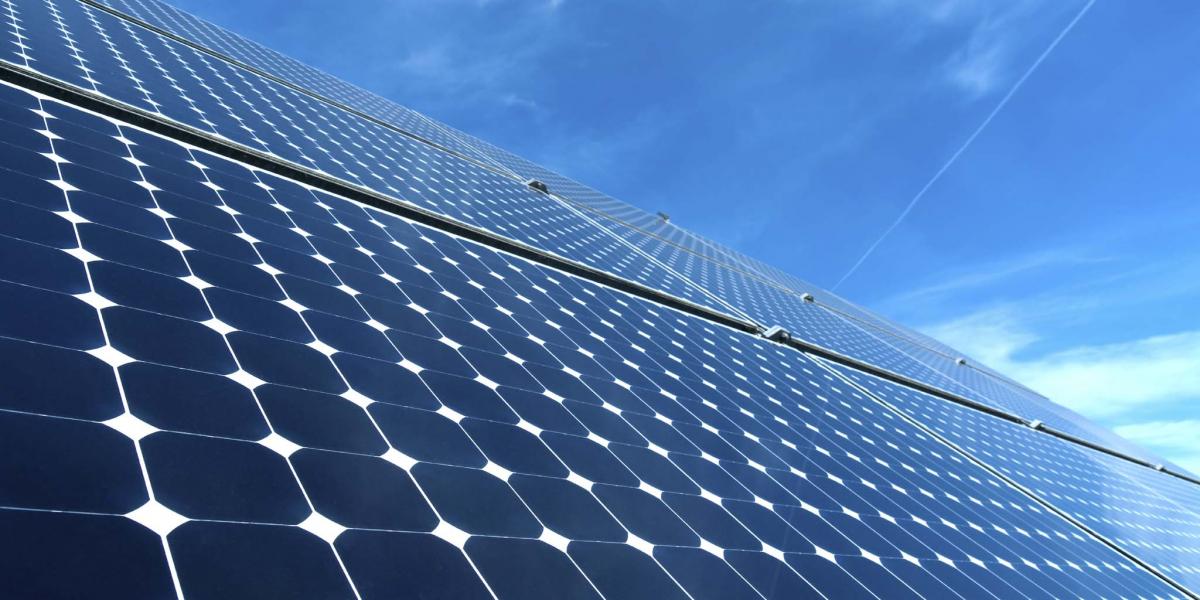
A PV module is a single panel consisting of 60 to 72 solar cells connected in series, with a typical power output of approximately 400W to 550W.
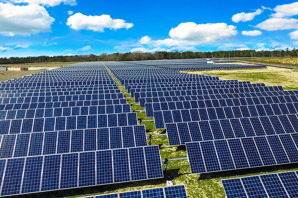
A PV array, on the other hand, is a complete power generation unit formed by combining multiple modules in series and parallel connections and mounting them on a support structure.
Efficiency and Performance
The Efficiency Bottom Line
When you get a module with a rated power of 580W, its dimensions are typically 2,278mm x 1,134mm, which is approximately 2.58 square meters.
Under Standard Test Conditions (STC), i.e., an irradiance of 1,000 W/m², a cell temperature of 25°C, and an air mass of AM 1.5, the conversion efficiency calculation for this panel is very rigid: output power divided by (area multiplied by 1000).
Although today's TOPCon cells can achieve efficiencies of 25.8% or even 26.4% on the production line, once encapsulated in glass and encapsulant film, they encounter the "Cell-to-Module (CTM) Loss".
This 2% to 3.5% efficiency loss is dictated by physical laws: the bus bars block approximately 2% of the light-receiving area, the glass and encapsulant reflect or absorb 1% to 2% of photons, plus the resistive losses in the internal circuitry.
Therefore, the final efficiency of the module delivered to you is typically between 22.5% and 23.3%.
Every 0.1% improvement in this range translates to savings of hundreds of acres in land lease costs and millions of dollars in support structure costs in gigawatt (GW)-scale power plants.
N-type TOPCon modules can now commonly achieve mass-produced efficiencies above 23.0%, while heterojunction (HJT) modules are challenging the 24.0% threshold. In comparison, traditional P-type PERC module efficiency mostly remains around 21.5%. If you choose high-efficiency modules for a 100-megawatt (MW) project, the BOS (Balance of System) costs for structures and cables alone can be reduced by 3% to 5%.
The High-Temperature Roadblock
Standard testing is done at 25°C, but in reality, modules under intense sunlight easily exceed 60°C or even 70°C.
The temperature coefficient for older P-type modules is about -0.35%/°C. For every 1°C increase in temperature, the power output drops by 0.35%.
At noon in summer, it's common for module temperature to be 45°C higher than the STC standard.
At that point, the power output directly shrinks by 15.75%, and a 500W panel instantly can only output 421W.
N-type modules, especially HJT technology, have optimized this coefficient to around -0.24%/°C. Under the same 70°C high temperature, the loss is only 10.8%.
To more accurately predict power generation, the industry introduced the NMOT (Nominal Module Operating Temperature) parameter, measured under conditions of 800 W/m² irradiance, 20°C ambient temperature, and 1 m/s wind speed. It typically ranges from 42°C to 45°C.
The advantage of modules with a low temperature coefficient is greatly amplified in hot desert regions. Measured data shows that in regions with ambient temperatures exceeding 40°C, TOPCon modules with a temperature coefficient of -0.29%/°C can achieve 3% to 4% higher lifetime energy yield compared to PERC modules with -0.35%/°C. This can be even more decisive for investment returns than the initial efficiency.
Low-Light Performance Tells the Truth
When incident light intensity drops to 200 W/m² or even lower, the module's series resistance (Rs) and shunt resistance (Rsh) begin to dominate.
High-quality modules have a very high shunt resistance, which can lock in the weak photogenerated current and prevent leakage, maintaining a relative efficiency above 97%.
Inferior modules can see their relative efficiency plummet below 90% under low irradiance.
This determines whether the inverter starts at 6:15 AM or waits until 7:30 AM to reach the startup voltage.
This small difference in startup time accumulates to over 400 hours of effective power generation time per year.
Furthermore, spectral response is also crucial. Thin-film or HJT modules have stronger absorption capabilities for blue and diffuse light, often showing a 1% to 2% power generation gain in cloudy weather compared to crystalline silicon modules.
Modules with excellent low-light performance can maintain a fill factor (FF) above 75% even under 200 W/m² irradiance. For high-latitude or foggy regions, this "early start, late stop" characteristic can increase the annual utilization hours per kilowatt of installed capacity by 50 to 80 hours.
Bifacial Payback
The "bifaciality" on the spec sheet refers to the ratio of rear-side efficiency to front-side efficiency, about 70% for PERC, increased to 80% for TOPCon, and as high as 85% or more for HJT.
However, the actual additional power generation depends entirely on the ground albedo. On an asphalt roof with only 10% albedo, the rear-side gain might be only 3% to 5%, or even be offset by racking shadows.
But on a roof painted with white high-reflectivity paint (albedo 70%) or snow (albedo 80%), the rear-side gain can instantly surge to 20% to 25%.
This also brings trouble to system design: if the inverter does not reserve sufficient DC oversizing capacity (DC/AC Ratio), the extra power will be wasted due to "clipping".
Typically, the inverter oversizing ratio for bifacial module systems should be designed at 1.2 to 1.3, or even higher.
Only when the module is mounted at a height exceeding one meter above the ground and with minimal front-to-back row shading can the rear-side diffuse light be uniformly received. Blindly using high-premium bifacial modules on low-albedo ground often fails to recoup the additional per-watt cost of even 1.5%.
System Funnel Effect
First is mismatch loss. According to the bucket theory, the current of a string of 28 modules is limited by the weakest one.
If the factory power binning is not strict, mixing modules from different current bins, or if a module's current drops due to local bird dropping shading, the entire string's output will be pulled down. This loss is typically 1% to 2%.
Next is cable loss. When transmitting a high current like 15 amps over long distances, the voltage drop in 4mm² photovoltaic-specific cables is not negligible. Well-designed power plants control DC line losses to within 1.5%, but this requires extensive use of 6mm² or even thicker cables.
Reliability and Durability
Warranty Hard Rules
The first things you get when buying modules are two warranty documents: one is a 12 or 15-year product and workmanship warranty, covering manufacturing, the frame not falling apart, and the backsheet not cracking.
The other, more critical one, is the 25 or 30-year linear power warranty.
The confidence for such long warranties comes from industry bibles like IEC 61215 and IEC 61730.
For P-type modules, manufacturers typically promise a first-year degradation not exceeding 2.0%, followed by a linear degradation of no more than 0.55% per year.
By year 25, the module's output power should be no lower than 84.8% of its initial nameplate power; the manufacturer compensates only if it falls below that.
Current N-type modules are even more aggressive: first year 1.0%, annual degradation 0.4%, and still at least 87.4% after 30 years.
These multi-decade promises are not just talk; they are based on models calculated from accelerated aging tests.
In actual operation, once the encapsulant (EVA) yellows or cell micro-cracks occur, the power curve can plummet like a roller coaster, possibly dropping to only 90% after 5 years.
Warranty Type | Typical Term | Key Promise Metric | Potential Failure Mode |
Product & Workmanship Warranty | 12-15 years | No visual defects, Electrical insulation qualified | Frame oxidation, Backsheet cracking, Junction box water ingress |
Linear Power Warranty | 25-30 years | Year 25 power ≥84.8% (P-type) | Cell corrosion, PID effect, Micro-crack propagation |
Brute Force Resistance
Modules installed on roofs must withstand not only wind but also snow. Standard mechanical load testing requires the module front to withstand a static load of 5400 Pascals (Pa).
This is equivalent to piling 1.3 tons of weight on a module surface of about 1.13 m × 2.27 m (2.5 sqm), simulating the pressure of 3 meters of dry snow or 1 meter of wet snow.
The rear side is required to withstand 2400 Pa of wind pressure, corresponding to a wind speed of about 130 km/h (Category 1 hurricane).
Some modules for extreme environments (e.g., offshore or high mountains) even push the front load standard to 7200 Pa.
More terrifying is the Dynamic Mechanical Load (DML) test, simulating high-frequency vibration of the module up and down 1000 times by strong wind. This can cause invisible micro-cracks inside the cells.
Once micro-cracks occur, the effective conductive area decreases, resistance instantly soars, and the temperature in that area can be 10°C to 20°C higher than the surroundings.
Thermal and Humidity Extremes
TC200 is the thermal cycling test. The module is placed in an environmental chamber, frozen to -40°C, then heated to 85°C, and cooled back to -40°C, repeated for 200 cycles.
This tests whether different materials (glass, aluminum frame, silicon wafer, encapsulant) will crack the module due to their different coefficients of thermal expansion.
If internal circuit connections are poorly soldered or silver paste adhesion is insufficient, an open circuit can occur in less than 50 cycles.
DH1000 is the damp heat test, "steaming" the module for 1,000 hours in a sauna-like environment of 85°C and 85% relative humidity.
At this point, moisture acts like a drill trying to penetrate the back sheet and edge sealant. Once moisture reaches the silver grid lines on the cell surface, electrochemical corrosion occurs, causing significant power degradation.
Coastal or floating solar plants often require testing up to DH2000 or even DH3000.
The Unbreakable Face
Standard 3.2 mm fully tempered glass, or the two layers of 2.0 mm heat-strengthened glass used in dual-glass modules, must pass hail impact tests.
The test standard involves firing ice balls with a diameter of 25 mm directly at the most fragile center and corners of the glass at a speed of 23 m/s (approx. 82.8 km/h).
That's not enough. With higher client demands, some projects now require resistance to hail diameters of 35 mm or even 45 mm.
If the glass isn't hard, even if it doesn't shatter, the underlying cells can be damaged by micro-cracks. Besides hardness, it also needs dust and acid resistance.
The glass surface is usually coated with an anti-reflective (AR) film 100 to 150 nanometers thick.
But near chemical plants, acidic deposits can corrode this film within 3 to 5 years, directly reducing transmittance by 3%, followed by power output.
Preventing Hot Spot Burnout
When a leaf or bird dropping completely blocks a cell, that cell stops generating power and instead becomes a load resistor, consuming power from other cells, instantly heating up. This is called a hot spot.
Without intervention, the local temperature can skyrocket to 150°C or even 200°C within minutes, burning through the backsheet or even causing a fire.
The bypass diodes in the junction box are the firefighters. A standard module typically has 3 diodes, dividing the cell string into three groups.
Once a group of cells is shaded and develops a reverse voltage, the corresponding diode turns on, allowing current to bypass the "bad" group, losing only 1/3 of the power, saving the module from burning.
A good junction box must achieve an IP68 protection rating, able to withstand immersion in one meter of water for one hour without leaking.
The diode junction temperature (Tj) tolerance must be above 200°C, and it must be fully sealed with potting compound for heat dissipation.
Material Aging Resistance
The white backsheet on the module's rear, if it's a conventional PET/PET structure, will yellow, become brittle, or even powder and fall off under intense ultraviolet (UV) bombardment in about 10 years, exposing live parts and sharply increasing the risk of leakage.
Now, high-end modules tend to use a dual-glass structure, meaning glass is also used on the back.
Although weight increases by 2 to 3 kg per square meter, glass is inorganic and doesn't age even in 50 years, with a water vapor transmission rate near zero (0.01 g/m²/day).
The encapsulant film also matters. Conventional EVA film decomposes in humid environments, producing acetic acid, which corrodes cell grid lines.
Therefore, for dual-glass or N-type modules, POE film or EPE co-extruded film is now more commonly used.
Although the cost is 2 to 3 RMB more per square meter, the anti-PID performance and moisture barrier properties are improved by 10 times or more, which is key to guaranteeing a 30-year lifetime.
Installation
Correct Positioning
In the northern hemisphere, true south (Azimuth 180°) is the absolute golden orientation.
For every 10° of deviation, the annual total irradiance received decreases by 0.5% to 1.5%.
For fixed-tilt racks, the optimal tilt angle is typically the local latitude ±3°. For example, at a latitude of 35°N, setting the installation tilt between 30° and 35° balances summer's high-angle direct sunlight and winter's low-angle diffuse light.
More critical is shading. The sun's altitude angle from 9:00 AM to 3:00 PM on the winter solstice (the day with the longest shadow of the year) must be calculated.
If the spacing between front and back rows of modules is less than 1.5 times the height of the front row's highest point, the bottom of the rear row modules will be shaded in winter.
Once the bottom row of cells is shaded by more than 1/3, the bypass diode activates, and instantly 1/3 of that module's power is lost; if shading occurs across a horizontal installation, the entire string might even stop working due to insufficient voltage.
For rooftop installation, leave at least a 10cm to 15cm gap between the module's lower edge and the roof surface. This is not just for cable routing but also to create a "chimney effect" for heat dissipation. Measurements show that the backsheet temperature of ground-mounted modules is 10°C to 15°C higher than raised installations. This directly reduces generation efficiency by 4% to 6% and accelerates backsheet aging.
Secure Mounting
Standard M8 stainless steel bolts, paired with aluminum alloy clamps, must be tightened to a torque strictly controlled between 16 N·m and 20 N·m.
For frameless dual-glass bifacial modules, which use specialized film clamps with EPDM rubber pads, the torque is typically lower, between 12 N·m and 15 N·m.
Overtightening can crack the glass, while undertightening causes vibration in the wind.
According to IEC 61215, mounting points are typically located at 1/4 of the module's long side, where it can bear the maximum 5400 Pa snow load and 2400 Pa wind load.
If, to save on racking costs, clamps are installed at the very ends of the long sides, the load-bearing capacity instantly halves.
In the face of a Category 8 gale or 20 cm of heavy snow, the module will undergo irreversible bending deformation from the middle or even be blown away.
· End Clamp: Width is typically 30mm to 40mm, must tightly grip the module edge, with a contact length not less than 50mm.
· Mid Clamp: Used between two modules, the gap left is typically 15mm to 20mm. This gap must account for the thermal expansion of the aluminum frame over a 50°C temperature difference, generally expanding about 1.2 mm per meter of length.
Connector Compatibility
Although they look similar, tolerances for male/female connectors from different brands can differ by 0.1mm to 0.2mm.
This tiny poor contact under high current can cause contact resistance to skyrocket from the standard 0.35 milliohms to over 100 milliohms.
According to Joule's Law (I^2R), a 15A current through a 0.1-ohm resistor generates heat power as high as 22.5W, enough to melt the plastic housing and ignite the roof within minutes.
Original manufacturer-matched metal terminals must be used.
During crimping, a dedicated ratchet crimping tool must be used, crimped completely until a "click" is heard. Pull-out force testing must exceed 310 Newtons to be qualified.
Accurate Voltage Calculation
The inverter's maximum input voltage is typically 1100V (residential/commercial) or 1500V (utility-scale).
Never calculate the number of modules in series based on the open-circuit voltage (Voc) at room temperature.
It must be calculated based on the historical lowest temperature at the site.
Assuming the module Voc is 49.5 V, the temperature coefficient is -0.25%/°C, and the local lowest temperature is -20°C.
Cable Specifications
DC cables must use photovoltaic-specific cables like PV1-F or H1Z2Z2-K, with a cross-sectional area of at least 4mm² (12 AWG).
For transmission distances over 50 meters or currents above 15A, it's recommended to directly use 6mm² (10 AWG).
The double-layer insulation of these cables can resist intense UV radiation and extreme temperatures from -40°C to 90°C, with a lifespan of up to 25 years.
During routing, cables must never be laid directly on rough tiles or cut edges of color steel sheets.
Micromotion abrasion from wind and sun can wear through the insulation layer within three years, causing a ground fault.
UV-resistant nylon cable ties or stainless steel cable clips must be used to secure cables to the side or back of the mounting rails, at intervals of 50 cm to 80 cm.
Also, pay attention to the bending radius; it must not be less than 4 times the cable diameter (typically at least 25 mm).
Sharp right-angle bends can damage internal copper strands, causing localized heating.
Grounding for Safety
The entire array must establish equipotential bonding. Each module's aluminum frame has a dedicated grounding hole.
Special stainless steel grounding washers with piercing teeth or yellow-green 4mm² grounding wires must be used to connect the module to the mounting rail, piercing the aluminum's oxide layer.
Then, all mounting rails must be connected to the building's lightning protection grounding network using 10 mm² or 16 mm² copper wire or flat steel.
The final ground resistance must be less than 4 ohms. This step is to prevent the module from suffering from PID (Potential Induced Degradation) and also to ensure that, in case of a lightning strike or leakage, current is quickly discharged to the earth rather than passing through a person or igniting dry grass.