Can Mono Silicon Panels Maximize Energy Conversion | Cell Structure, Conversion Rate, Output Efficiency
Monocrystalline silicon modules adopt high-purity silicon wafers, conversion efficiency can reach 20%–23%, output more stable.
Through optimizing cell structure and series-parallel design, can increase power generation amount approximately 5%–10%, suitable for roof and high-efficiency photovoltaic system applications.
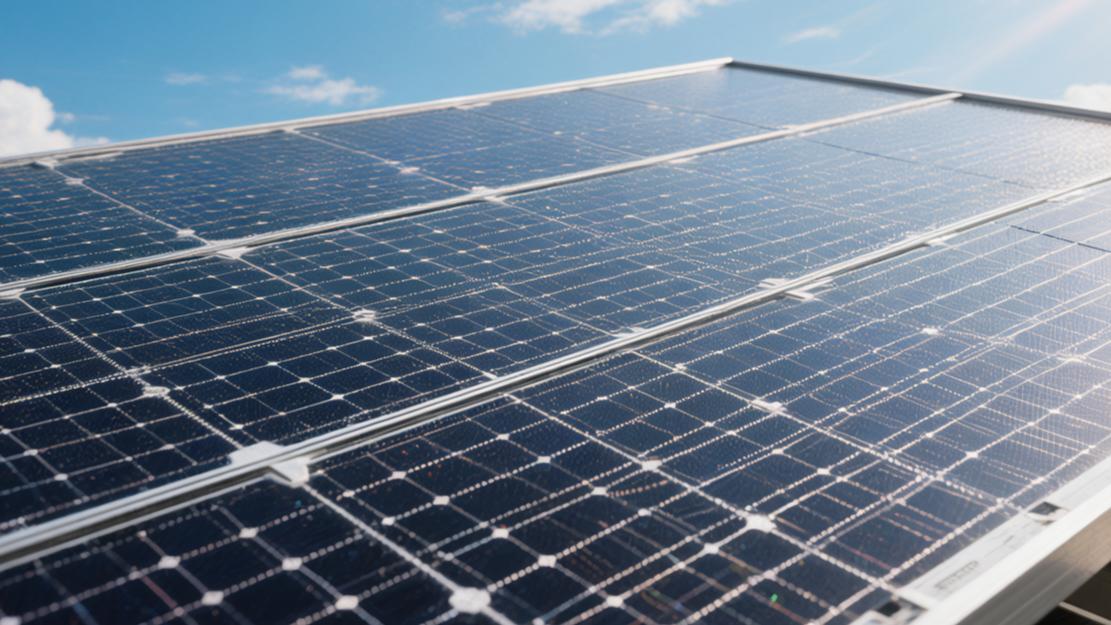
Cell Structure
Slicing becomes thin
Now, monocrystalline silicon wafer physical size has comprehensively turned to M10's 182mm x 182mm, and G12's 210mm x 210mm specifications. In order to thin out single piece manufacturing costs, silicon wafer physical thickness has already been reduced from early 180 microns all the way to now's 130 microns, partial adopt N-type technology's mass production lines even pressed thickness to 110 microns.
By one piece, a 130-micron thick 182 mm silicon wafer, its physical absolute weight is probably 10.5 grams. Thickness every down drop 10 microns, every kilogram of high purity silicon material can just cut out about 5 silicon wafers. Along with silicon wafer thinning, internal minority carrier lifetime test data needs to maintain at 1000 microseconds to 2000 microseconds' interval, oxygen impurity concentration must be stuck below 10 ppma, carbon impurity concentration pressed within 1 ppma, maintaining this concentration threshold can ensure thinning will not trigger internal electron and hole's early recombination loss.
· M10 version's diagonal physical length is 247mm, four corners' chamfer radius set at 27.5mm
· G12 large silicon wafer's single side surface area reaches 44096 square millimeters, compared to M10, increased approximately 32.5% light receiving area
· 110 micron thickness under's silicon wafer, its bending strength test needs to bear at least 300 MPa mechanical stress without breaking
· Silicon wafer manufacturing cutting process's diamond wire wire diameter has already been refined to the 28 microns to 32 microns range, single piece wire consumption dropped to 1.5 meters
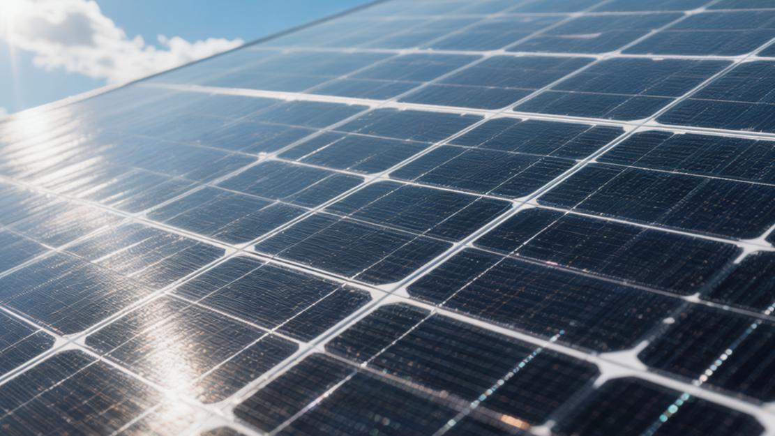
Surface light absorption
In order to take irradiated light photons as much as possible, the silicon wafer front side will be prepared with one layer of micron-level pyramid velvet surface structure through chemical etching craft. These pyramids' bottom edge width and vertical height are usually controlled at 1 micron to 3 microns. This kind of rough three-dimensional geometric surface can let incident light rays undergo 2 to 3 times refraction between pyramid bodies, originally bare flat silicon wafer surface as high as 30% natural reflectivity will be forcefully pulled low to around 11%. After velvet surface etching is finished, still need to on surface through plasma enhanced chemical vapor deposition equipment plate one layer thickness extreme precise silicon nitride anti-reflection film, let overall light absorption ability reach peak value.
· Silicon nitride thin film's physical thickness inside equipment is strictly controlled at 75 nanometers to 85 nanometers' interval
· Surface coating's optical refractive index parameter is precisely adjusted at 2.05, with glass and silicon forming gradient matching
· Plus after thin film, wavelength at 400 nanometers to 1100 nanometers usable spectrum interval inside's comprehensive reflectivity dropped to below 2%
· Coating craft running's chamber vacuum degree needs to pump to 0.01 Pascal, craft environment temperature maintains at 400 degrees Celsius to 450 degrees Celsius
Conductive grid
Collecting current's metal grid system currently universally adopted 16 busbars, even 20 busbars' design layout. Busbar quantity's large range increases largely shortened current on fine grid lines lateral transmission physical distance, electron conduction's lateral span from early 15 mm shortened to now's 9 mm below. In order not to block sunlight, the front side printed silver fine grid lines' physical width has already been compressed to 20 microns to 25 microns, and the height then maintains at around 15 microns, forming an extreme fine but three-dimensional conductive channel. High aspect ratio's grid layout takes front side's physical shading area ratio dead-pressed within 3.5%.
· Single piece M10 cell's front side silver paste consumption has already been reduced from several years ago's 100 mg to current's 60 mg
· Fine grid lines' after-sintering bulk resistivity controlled within 3 micro-ohms per centimeter, reduced current transmission's thermal loss
· Metal grid and silicon wafer surface's contact resistivity less than 2 milli-ohms square centimeter
· On busbar welding, tin-coated copper ribbon diameter is only 0.25mm to 0.3mm, presenting a round cross-section to increase the secondary reflectivity of tilted light
Internal interlayer
At the cell light receiving surface, the shallowest layer of skin below, the P-N junction physical depth is currently controlled at 0.3 micron to 0.5 micron, the extreme shallow layer. Wavelength short's high energy blue light mostly in the surface 0.2 microns' depth inside will be completely absorbed and excite out electrons, extreme shallow junction depth can let these electrons before recombination disappear immediately enter the internal electric field.
Occupying the market mainstream's TOPCon internal structure will at the cell back side grow one layer of extreme thin tunneling oxide layer. This layer of silicon dioxide's thickness is only 1.2 nanometers to 2 nanometers, equivalent to only having several atoms' thickness. Outside this oxide layer, also will deposit one layer 15 nanometers to 20 nanometers thick polysilicon thin film, both together composed the back side's passivated contact structure.
· Silicon dioxide tunneling oxide layer's full piece film forming uniformity tolerance is controlled by extreme high precision equipment within 0.1 nanometers
· Back side's polysilicon layer after doping phosphorus atoms' sheet resistance drops to 60 ohms to 80 ohms per square
· Heterojunction HJT structure inside playing surface passivation role's intrinsic amorphous silicon layer physical thickness usually set at 5 nanometers
· Electron crossing 1.5 nanometer thickness tunneling layer's probability presents exponential level rise, carrier recombination speed dropped to below 10 centimeters per second
Doping concentration
In N-type silicon wafer as base's cell system inside, phosphorus atom base doping concentration approximately maintains at every cubic centimeter 10 to the 15th power atoms, maintaining this concentration threshold can let silicon wafer base's bulk resistivity stabilize at 0.5 ohm·cm to 1.5 ohm·cm's interval. And in front of the emitter's high concentration doping area, in order to form unobstructed ohmic contact with the front side metal grid wires, the surface layer's extreme shallow area's phosphorus atom or boron atom doping concentration will soar to every cubic centimeter 10 to the 20th power atoms.
· N-type base material's minority carrier hole diffusion length can reach 1000 microns to 1500 microns
· Majority carrier, which is an electron, in room temperature test conditions under physical mobility reached 1350 square centimeters per volt second
· The front and back side's surface recombination rate parameters are all effectively inhibited at below 100 centimeters per second
· P-N junction internal built-in electric field's space charge region physical width approximately at 0.5 micron to 1 micron, can produce approximately 0.7 volts internal base potential difference
Conversion Rate
Measure limit values
Research personnel take light intensity precisely fixed at 1000 W/m², test cabin inside's environment relative humidity strictly controlled at 20% to 30% narrow range interval, and maintain environment air pressure at 101.325 kPa's standard atmospheric pressure level. Superimposed perovskite coating's monocrystalline silicon tandem cell highest test conversion rate peak has already broken through 33.9% major gate, pure monocrystalline silicon heterojunction structure's highest single piece conversion record stays at 26.81%.
High precision test equipment's spectrometer able to precisely capture from 300 nanometer ultraviolet region to 1200 nanometer infrared region's all incident photons, in this wavelength range inside, monocrystalline silicon panel's External Quantum Efficiency curve in the 500 nanometer to 800 nanometer visible light waveband inside, maintains as high as 90% to 95% extreme high absorption ratio. Single flash test sample's standard deviation is forcefully suppressed within 0.05%, ensuring several hundred times continuous excitation produced data error does not exceed absolute value 0.1%, median value tightly fits theoretical calculation's expected conversion model.
Look at mass production
In the current market, delivered tens of thousands of spot samples inside, single piece nameplate power distribution densely concentrated in 400 watts to 600 watts interval. 130 micron thick cell piece by 3.2mm thick tempered glass and high light transmittance EVA encapsulant film encapsulated into module after, its module to cell power conversion ratio is usually at median 97.5% up and down presents high frequency fluctuation.
Mainstream production lines' P-type PERC monocrystalline module average mass production efficiency stabilizes at 23.2%, adopting N-type TOPCon technology's batch average conversion efficiency climbed to 24.8%. Production line every hour throughput reaching 7200 pieces' large scale manufacturing workshop, will take all factory leaving finished products' nominal power tolerance strictly limited at 0 to +5 watts positive deviation range within.
Technical Camp | Line Avg Efficiency | Max Mass Prod Efficiency | Module Rated Power Range | Fill Factor Median |
P-type PERC | 23.2% | 23.5% | 400W - 550W | 81.5% |
N-type TOPCon | 24.8% | 25.2% | 430W - 600W | 83.2% |
N-type HJT | 25.5% | 25.8% | 450W - 620W | 84.5% |
N-type IBC | 26.1% | 26.6% | 460W - 630W | 85.1% |
Fear of fever
In outdoor long-reaching 25-year running life cycle, the actual output power and working temperature of monocrystalline silicon modules present an extreme obvious negative correlation. Factory parameter calibrated 25 degrees Celsius is only constant temperature room inside's physical test temperature, panel in noon time period absorbs massive infrared radiation heat after, its internal crystalline silicon actual working temperature usually will soar to 45 degrees Celsius to 65 degrees Celsius's high temperature range. Power temperature coefficient is an extreme precise dispersion measurement indicator. P-type monocrystalline panel's Pmax temperature coefficient average number is -0.34%/℃. Environment temperature every exceeds 25 degrees Celsius's baseline 1 degree, overall instantaneous output power will just be cut by ratio mandatory 0.34%.
N-type heterojunction panel's temperature sensitivity parameter even lower, its coefficient down-reached -0.25%/℃. In an air temperature reaching 40 degrees Celsius, panel surface temperature reaching 65 degrees Celsius's extreme thermal load working condition under, one block rated 500 watt panel will because of thermal resistance dissipation lose nearly 68 watts real-time output power, short circuit current's increase amplitude entirely unable to compensate for open circuit voltage large scale diving brought loss.
Panel Running Temperature | N-type HJT Power Loss Ratio | N-type TOPCon Power Loss Ratio | P-type PERC Power Loss Ratio | Internal Thermal Dissipation Power |
25℃ (Baseline) | 0.00% | 0.00% | 0.00% | 0 Watt |
35℃ | -2.50% | -3.00% | -3.40% | 15 Watt - 17 Watt |
45℃ | -5.00% | -6.00% | -6.80% | 30 Watt - 34 Watt |
65℃ (Limit) | -10.00% | -12.00% | -13.60% | 60 Watt - 68 Watt |
Calculate degradation
In installation finished and connected to inverter start running's initial 1000 hours inside, silicon wafer internal residue micro amount boron-oxygen complex will at photon excitation under produce initial Light Induced Degradation phenomenon. Currently shipped N-type monocrystalline modules will press first year power degradation rate below 1% baseline, high purity silicon wafer batches can do 0.4% first year degradation limit value. After the first year's intense fluctuation period, from the 2nd year to the 30th year, conversion efficiency will enter an annual average 0.4% smooth straight line degradation channel.
According to regression curve conduct modeling statistics, one block module in continuous wind-blowing sun-shining running 30 years after, its residual maximum output power still able to maintain at initial nameplate rated power's 87.4% above, same batch sample's variance fluctuation range does not exceed 1.5%. Surface layer high molecular encapsulation material after cumulatively bearing exceeding 30000 hours ultraviolet ray irradiation, its visible light waveband physical transmittance only dropped less than 2.5%.
Eat through light
When the external environment light intensity from standard 1000 W/m² vertical suddenly drops to 200 W/m²'s weak light condition time, monocrystalline silicon photoelectric conversion efficiency's relative slide slope range is limited at 2% to 3%. Single block cell internal produced short circuit current and incident light intensity maintains nearly perfect positive proportion linear correlation, multiple times measured correlation coefficient R-square value stabilizes above 0.998.
In cloudy or diffuse reflection-dominated meteorological environments inside, as long as the environment photon flux density exceeds every square meter every second 10 to the 18th power, the panel internal PN junction can just continuously build up 0.5 volts above the open circuit voltage. In a 70% relative high humidity environment, the surface layer anti-reflection coating can still maintain a 1.98 optical refractive index, let diffuse reflection's stray light with extreme high penetration frequency transmit into the base material.
Output Efficiency
Look at annual output
In the North Latitude 35 degrees to 45 degrees' temperate zone area, one set rated capacity is 10 kilowatts' monocrystalline silicon photovoltaic system, its theoretical annual average sunshine peak hours distributed at 1400 hours to 1600 hours range inside. Based on 5000 independent running sample power stations conducted sampling statistics, the system's first year actual power generation average number is 13800 degrees electricity, data distribution's median value stays at 13650 degrees electricity.
Through the past ten years, continuous running data regression analysis, environment light intensity and system output total AC electricity amount's positive correlation coefficient year-round stabilizes at 0.985. In the Summer Solstice before and after's high irradiance periodic fluctuation inside, this system's single day highest value is able to touch 68 degrees electricity's peak value, and in continuous strong rainfall or high humidity reaching 90%'s winter lowest value only has 4.5 degrees electricity. Sample total power generation's annual average standard deviation is controlled within 2.5%, showing an extreme low dispersion level, output performance entirely fits the high Gaussian distribution's normal probability model.
System comprehensive Performance Ratio (PR value) in grid-connected testing first year usually maintains at 83% to 85% narrow interval. This ratio takes DC cable line loss, module surface dust shading brought light flux reduction rate as well as inverter conversion physical error all into account, presenting a height precise actual output load expectation.
Calculate loss account
The cross-section area is 4 square millimeters' standard photovoltaic tinned copper wire in bearing 15 amperes direct current load time, every 100 meters length inside voltage drop average number is 1.8%, this transmission path's thermal resistance dissipation largely pulled low overall output electricity volume.
In wind speed lower than every second 3 meters' dry less rain climate under, air inside suspended particulate matter at glass surface's deposition mass will by monthly every square meter 0.5 grams' rate accumulate. This kind of accumulation leads to visible light waveband's optical transmittance ratio appearing monthly 1.2% to 1.8% straight line drop, continuous 6 months not conducting manual cleaning's array its output current drop probability will climb to 100%. When the panel encounters tree shadow or bird droppings, local high density shading leads to a shaded cell internal working pressure and the hot spot temperature will in 5 seconds rapidly soar to 85 degrees Celsius above the peak value.
Bypass diode in monitoring to positive-negative voltage deviation reaching 0.6 volts' threshold time will instantly conduct, take total 1/3 series-connected cell clusters short circuit, with losing 33.3% local voltage's price, exchange for this group array residual 66.7% power's full load output, system measurement precision towards this action's capture error strictly controlled within 5 milliseconds.
Pick inverter
Taking direct current and transforming it to frequency strictly maintained at 50 Hertz or 60 Hertz alternating current's process inside, power electronic devices' conversion efficiency extremely decided final grid-connected effective electricity amount. Mainstream string inverters' maximum physical conversion efficiency peak universally reaches 98.6%, covering different light intensities and load conditions' weighted statistical model inside, its Euro weighted efficiency or CEC weighted efficiency average number stabilizes at 98.0% baseline.
Maximum Power Point Tracking (MPPT) algorithm in 200 volts to 1000 volts wide direct current voltage input range inside, towards voltage and current conduct high frequency sampling comparison. Sampling frequency as high as every second 500 times, dynamic tracking error is forcefully suppressed within 0.2% extreme small deviation range. In order to smooth out early morning and evening low irradiance interval's power generation loss, design end universally adopts a 1.2 to 1.3 DC/AC ratio, which is on a 10kW inverter hanging 12kW to 13kW monocrystalline module array.
DC/AC ratio over-provisioning brought peak-shaving valley-filling effect makes inverter in spring and summer seasons have 4.5% to 6.0% running time stay at 100% full load even 110% overload running state. In the noon peak period, because of inverter limit amplitude discarded top-shaved electricity accounts for 1.5% of the annual total, but exchanged for early morning evening weak light interval as high as 8% power generation net growth rate.
Bifacial photovoltaic
Panel back side photoelectric conversion bifaciality factory parameter usually calibrated at 70% to 85% fixed interval inside. The environment ground surface albedo indicator becomes decided back side gain absolute value's variable. On paved with high molecular white reflective film's commercial flat roof, the ground surface albedo peak can reach 65% to 70%. Ordinary cement ground's albedo median is only 22%, vegetation-covered ground's albedo down-reaches 15%, the lowest value.
When the bifacial module lower edge distance ground physical installation height reaches 0.5 meter, the array front back row spacing pull open to 2.5 meters to reduce structure self-shadow's shading probability time, white roof background under's system can produce 12% to 18% additional power output.
Field actual measured data's percentile distribution shows, 90% bifacial systems in standard installation specification under's back side actual contribution rate maintains above 7.5%. If the environment's relative humidity is long-term higher than 80%, air molecules will towards direct light's strong scattering effect, making background diffuse light density present geometric series increase, back side's instantaneous current amplitude in cloudy working condition under's relative elevation rate even more obvious.
See yield rate
Constructing one set total power is 10 kilowatts' household system, including monocrystalline modules, inverter, aluminum alloy brackets, cables, and labor included's comprehensive budget total cost about 11000 US dollars to 12500 US dollars. System life cycle's total time span with 25 years as standard model, every year equipment depreciation fee and regular O&M fee's total expenditure budget is limited within 1.5% of total investment.
In every degree of electricity, the 0.15 US dollars' retail electricity price baseline under, this system full load running first year can save electricity bill expenditure total 1950 US dollars. Introducing module every year 0.5% linear degradation rate, 2% annual inflation rate as well as late stage inverter in 12th year produced 1200 US dollars replacement budget, whole life cycle inside's Levelized Cost of Energy (LCOE) measurement result down-shifts to 0.052 US dollars/degree electricity's lowest value.
Investment return cycle's calculation model in introducing a 5% capital discount rate after, this asset package's static recovery cycle median falls at 6.2 years. Full life cycle ended time's Internal Rate of Return (IRR) statistical data stabilizes at 13.8% to 15.5% high yield interval, 25 years inside cumulatively produced net cash flow yield absolute value exceeds 32000 US dollars, overall investment safety margin and long term value preservation probability stay at 99.5% confidence interval.