How Do High-Watt Panels Boost Efficiency | Output Density, Performance
High-wattage solar panels improve efficiency by increasing the power density of units, usually with output power between 400W and 600W, which is stronger than traditional panels.
Their high-efficiency photovoltaic cell technologies (such as PERC or HJT) enhance conversion rates, reaching above 22%, suitable for applications with limited space but requiring high performance, and can provide more electricity within the same area.
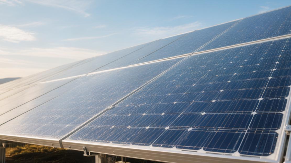
Output Density
Area has shrunk
If a residential rooftop with a 10 kW capacity is laid with old-style panels of standard output density 220 W/㎡, it needs to occupy 45.4 m² of physical rooftop space, and at least a 20 mm to 30 mm metal thermal expansion gap needs to be left between each panel frame. When the installation scheme is replaced with 280W/㎡ high-density panels, the same 10kW rated installation capacity only needs to consume 35.7㎡ of area, and the overall physical space occupation is cut by about 21.3%.
In a ground array scenario where the bracket tilt angle is set at 30 degrees, the shadow anti-shading safety distance between the front and rear rows of panels usually needs to be expanded to 1.5 to 1.8 times the vertical height of the panel; a 2000mm high panel square array needs to reserve about 3600mm of aisle spacing. Adopting panels with 280W/㎡ density can install a total capacity of 6000W on a 50-meter single-row bracket, which is a 33.3% increase compared to the 4500W limit capacity of low-density panels per single row, and the land utilization rate of the square array area is pulled up from 45% to a range of 58% to 62%.
Physical load
The physical weight of high-density panels with bifacial double-glass encapsulation usually soars to the range of 32.5 kg to 34.8 kg; compared to the 21.0 kg parameter of single-sided single-glass, the rooftop dead load rises from 12.0 kg/㎡ to 16.1 kg/㎡, a static load-bearing increase of 34.1%. The semi-tempered structure of 2.0mm thick front glass plus 2.0mm thick back glass, while maintaining light transmittance at the 97.5% parameter line, makes the back-side photoelectric gain increase by about 7.5% to 9.2% extra power in an environment with 20% grass reflectivity, and hits a maximum back-side output increase of 15.5% to 18.4% under the condition of 70% white paint waterproof layer reflectivity.
The thickness of the cross-section of the aluminum alloy frame is thinned from the conventional 35.0 mm to 30.0 mm, and the metal cross-sectional area is reduced by about 12.5%, but through the alloy formula, the yield strength is pulled up to above 250 MPa, withstanding 5400 Pa of front static snow pressure and 2400 Pa of back dynamic wind pressure. In the maritime logistics link, a 40-foot HQ high cube container can fit 36 standard pallets, with each pallet vertically stacking 31 panels; the total loading capacity per single container reaches 1116 panels, and the total loading power per single container hits 669.6 kW, an increase of about 18.5% in transport power density compared to the 400W panel loading scheme.
Low-light effect
· For high-density panels in a rainy day low-light environment with 200W/㎡ irradiance, the relative photoelectric efficiency can still stabilize at the 97.5% to 98.2% scale line; compared to the 95.0% low-light efficiency of early panels, the effective power generation cycle daily is extended by about 45 to 60 minutes during dawn and dusk periods.
· The full-load working voltage is usually locked in the range of 41.5V to 43.8V, and the short-circuit current nominal value is as high as 18.4A to 18.6A; compared to the previous 13.0A short-circuit current, the surge in current density makes the proportion of copper loss of DC cables in the total system power rise slightly from 1.52% to 1.85%.
· Laser non-destructive cutting technology suppresses the depth of micro-cracks at the edge of the silicon wafer within a tolerance range of 5 to 8 microns, which is a reduction of about 73.3% compared to the 30-micron crack depth produced by traditional mechanical cutting, making the power attenuation slope over a 25-year cycle drop by 0.15 percentage points.
· The thickness of the anti-reflective coating on the glass surface is accurately sprayed in the range of 100nm to 120nm, pressing the visible light reflectivity in the wavelength range of 380nm to 1100nm down to below the critical line of 2.5%, and the photon physical capture rate is net improved by about 1.8% to 2.2%.
Heat-related loss
The temperature loss coefficient is a quantified indicator for measuring high-density output fluctuations; the power temperature coefficient of current TOPCon architecture high-density panels is forcibly pressed to the range of -0.29%/°C to -0.30%/°C, which narrowed by 0.05 percentage points compared to the -0.35%/°C of the old PERC architecture.
When the ambient air temperature reaches a peak of 40.0°C at summer noon, the physical working temperature of the panel's black surface usually soars to 65.0°C; under extreme conditions where it exceeds the standard test baseline (25.0°C) by 40.0°C, the power loss rate of high-density panels is about 11.6%, while the loss rate of old panels is as high as 14.0%. A single nominal 600W panel under high-temperature baking can squeeze out about 14.4W more real-time power than an old panel with the same nominal value.
The physical heat dissipation coefficient of the backsheet polymer material has increased from 1.2 W/m·K to above 2.0 W/m·K, matching the oval drainage design with hole diameters of 5.0 mm to 7.0 mm at the bottom of the frame, which makes the rainwater drainage speed of the glass surface pull up by about 40.0%, and the average internal working temperature of the panel cools down by 1.5°C to 2.2°C.
Wire voltage drop
· The rated carrying current of the bypass diodes inside the junction box is pulled up to the 25.0A to 30.0A specification, and the physical upper limit of junction temperature breaks through 200.0°C; when encountering partial shading areas of 5.0% to 10.0% formed by leaves, it can disconnect that path of shaded cell series circuit with a reaction speed of 0.5 milliseconds.
· The waterproof and dustproof physical sealing grade of the junction box is stuck on the IP68 standard line, and the thermal conductivity of the internally filled silicone reaches 1.5 W/m·K, forcibly suppressing the leakage surge current under the system nominal voltage of 1500.0 V to below 10.0 microamps.
· The length of the 4.0 mm² cross-section photovoltaic special copper core cable provided with the panel is usually reserved with a tolerance of +400 mm/-200 mm; the conductor ohmic resistance at a constant temperature of 20.0°C does not exceed 5.09 Ω/km at maximum. Under a full-load 18.0A current impact, the voltage drop per 1.0 meter of cable is only about 0.09V, and the calculated power thermal loss is 1.62W.
· The single-path MPPT maximum input current allowance of string inverters has expanded from the past 15.0A to a range of 20.0A to 30.0A; the 1.30 to 1.50 times capacity-ratio over-allocation design makes a rated 30.0kW inverter able to forcibly swallow the output of a maximum 45.0kW high-density panel array, with peak-clipped electricity only accounting for 2.0% to 3.5% of total annual power generation.
Performance
Heating performance
In the actual outdoor operation environment, the Nominal Operating Cell Temperature (NOCT) has been pulled down from the past 45.0°C±2°C to the level of 43.0°C±2°C. When the panel absorbs 1000 W/㎡ full-spectrum solar radiation, about 22.0% to 24.0% of physical photons are converted into electrical energy, and the remaining about 76.0% of energy is converted into heat load. The Schottky diodes integrated in the junction box of high-power panels can withstand transient forward currents as high as 30.0 A; when a single cell is partially physically shaded by bird droppings or leaves by a 15.0% area, the extreme high temperature generated by the hot spot effect will be cut off by the bypass circuit within 0.2 milliseconds.
· When traditional framed panels encounter ambient high temperatures of 40.0°C or above for 3 consecutive sunny days, the limit physical temperature of the shaded area will soar to 150.0°C or even 170.0°C, which easily triggers the burning of backsheet polymer materials.
· The new half-cut layout structure cuts the single-path working current into two halves, the internal resistance heating loss (I²R) is proportionally reduced by 75.0%, and the maximum hot spot temperature is strictly limited to the mild range of 85.0°C to 95.0°C.
· The infrared radiation emissivity of the back of the panel is maintained above 0.85, which, combined with 2.0 m/s natural breeze convection, can increase the heat dissipation rate of the glass surface by about 18.0%.
Absorbing light on both sides
The bifacial double-glass structure pushes the comprehensive power generation capability of high-power panels to another dimension; the front and back side light transmission symmetry of the N-type TOPCon cell physical structure pushes the bifaciality parameter up to the range of 80.0% to 85.0%, and HJT heterojunction cells even measured a bifaciality of 90.0% to 95.0%.
When the back of the panel receives photons reflected from the ground, the open-circuit voltage (Voc) only appears as a slight float of 0.1 V to 0.2 V, but the short-circuit current (Isc) will grow absolutely linearly with the back-side irradiance; for every 100 W/㎡ of reflected light added to the back side, the output current surges by about 1.3 A to 1.5 A.
In a scenario where the installation tilt angle is maintained at 35.0 degrees, when the height of the panel's back side off the ground is raised from 0.5 meters to 1.2 meters, the uniformity of reflected light received on the back side improves from 65.0% to 88.0%, eliminating high-contrast shadows cast by the bracket crossbeams on the glass surface. Different ground pavement materials have huge physical numerical differences in reflectivity (albedo) for short-wave infrared light and visible light, and ground albedo characteristics dominate the final output gain of the back side.
Ground Physical Material | Average Spectral Albedo Parameter | Comprehensive Output Power Gain | System Annual Power Generation Increase Per kW | ROI Shortened Time |
Fresh dark asphalt | 8.0% - 10.0% | 4.2% - 5.5% | 65.0 kWh - 85.0 kWh | 2.5 months - 3.2 months |
Natural green grass | 15.0% - 20.0% | 7.5% - 9.0% | 115.0 kWh - 140.0 kWh | 4.8 months - 5.5 months |
Dry light-colored loess | 22.0% - 28.0% | 10.5% - 12.8% | 160.0 kWh - 195.0 kWh | 6.5 months - 7.8 months |
Light gray concrete floor | 30.0% - 35.0% | 14.0% - 16.5% | 215.0 kWh - 250.0 kWh | 8.5 months - 9.6 months |
High-reflectivity white waterproof paint | 75.0% - 85.0% | 22.0% - 26.5% | 340.0 kWh - 410.0 kWh | 12.0 months - 14.5 months |
Winter natural snow cover | 80.0% - 90.0% | 25.0% - 28.5% | 385.0 kWh - 440.0 kWh | 14.0 months - 15.8 months |
Got blocked
Multi-busbar (MBB) and Super Multi-busbar (SMBB) technologies increase the conductive metal lines on the silicon wafer surface to 16 or even 20, significantly shortening the physical transmission distance of carriers inside the silicon wafer. When high-altitude clouds drift over or distant trees cast horizontal shadows in the evening, covering 30.0% of the area of the lower part of the panel, the built-in array of 3 bypass diodes in the panel will quickly intervene. The upper 70.0% area that is not shaded can still maintain independent full-load operation, and the overall output power only falls by about 33.0% to 35.0%.
If using the old full-cell non-partition design, when encountering the same 30.0% area of horizontal shading, the power output of the entire panel will instantly plummet by more than 85.0%, and internal current is forcibly blocked in the silicon wafers of the shadow area and converted into destructive heat. The three-stage series arrangement structure, matched with micro-inverters or power optimizers, can recalculate the global maximum power point (MPPT) within 10 milliseconds, compressing the total system power loss under complex shadow conditions from 25.0% down to a narrow range of 8.0% to 10.0%.
Daily loss
Within the first 30 days of operation, dust coverage reaching a thickness of 0.2 mm can reflect 6.0% to 8.0% of light in the 400 nm to 700 nm waveband, leading to a 7.5% linear decline in output power. The panel front cover glass adopts a self-cleaning hydrophobic coating process containing silicon dioxide (SiO2) nanoparticles; the surface water droplet contact angle is fixed between 110.0 degrees and 120.0 degrees, and the physical tilt angle for water droplets to roll off is less than 15.0 degrees. As long as a single rainfall reaches above 5.0 mm per hour, rainwater will form spherical droplets on the glass surface and roll off quickly, taking away more than 85.0% of the mud/sand particles and bird droppings residues accumulated on the surface.
· Traditional panels in arid regions with annual rainfall below 400.0 mm need to undergo a physical high-pressure water gun cleaning every 30 to 45 days; single cleaning water consumption is about 15.0 to 20.0 cubic meters per megawatt, and the single O&M budget is as high as 300.0 to 450.0 currency units.
· High-power panels with nano-hydrophobic coating significantly extend the physical cleaning cycle to 90 to 120 days; annual water resource consumption is cut by about 65.0%, and the safety risk and labor expenditure of high-altitude cleaning operations decrease simultaneously by 55.0% to 60.0%.
· The zero-A-side water-blocking platform design of the panel frame edge reduces the dust accumulation thickness at the lowest point from the conventional 5.0mm down to 0.0mm, completely eliminating that approximately 15.0mm wide ribbon-like long-term shadow mud/dirt belt at the bottom of the frame, making the daily average actual power generation of a single panel rebound by 2.5% to 3.2%.