How Long Do Polycrystalline Solar Panels Last
The average service life of polycrystalline silicon solar panels is typically 25 to 30 years.
In practical applications, their power generation efficiency naturally degrades by only 0.5% to 0.7% per year.
Even after 25 years of continuous use, they can still maintain approximately 80% of their initial power generation capacity.
The 25-Year Benchmark
25-Year Standard
The physical operating parameters of polycrystalline photovoltaic modules over a quarter-century are based on qualified data from dual testing under International Electrotechnical Commission standards IEC 61215 and IEC 61730.
In a constant temperature and humidity laboratory accelerated aging chamber, a standard-sized polycrystalline silicon panel (1650 mm x 992 mm, net weight 18.5 kg, 60 cells) must endure a full-load 1000-hour damp heat test at an ambient temperature of 85°C and relative humidity of 85%, superimposed with 200 thermal cycles of physical shock from extreme cold at -40°C to high heat at 85°C.
Under ultra-high load temperature difference stress, polycrystalline silicon modules produced by Tier 1 factories are still mandatorily guaranteed to maintain an actual measured output power above 80.7% of the factory-rated peak power at the end of the 25th natural year.
Taking a residential rooftop stand-alone system with an installed capacity of 6.6 kW as an example, assuming the total AC side power generation in the first year of grid-connected operation is 8,500 kWh, and calculating based on a fixed annual linear degradation rate of 0.65%, the actual net power generation of the system in the 25th year after 25 cycles of seasonal rotation will still reach 7,123 kWh. The cumulative total power generation over the 25-year cycle will steadily surpass the 195,000 kWh milestone.
The microscopic grain boundary structure inside polycrystalline silicon wafers undergoes slight Light-Induced Degradation (LID) after absorbing high-energy photons throughout the day. The power drop in the first year usually ranges between 2% to 2.5%. From the 24th month onwards, the atomic arrangement inside the panel tends toward a steady state, and the subsequent annualized power deviation rate is strictly limited within a narrow range with a mean squared error of 0.05.
Internal Aging
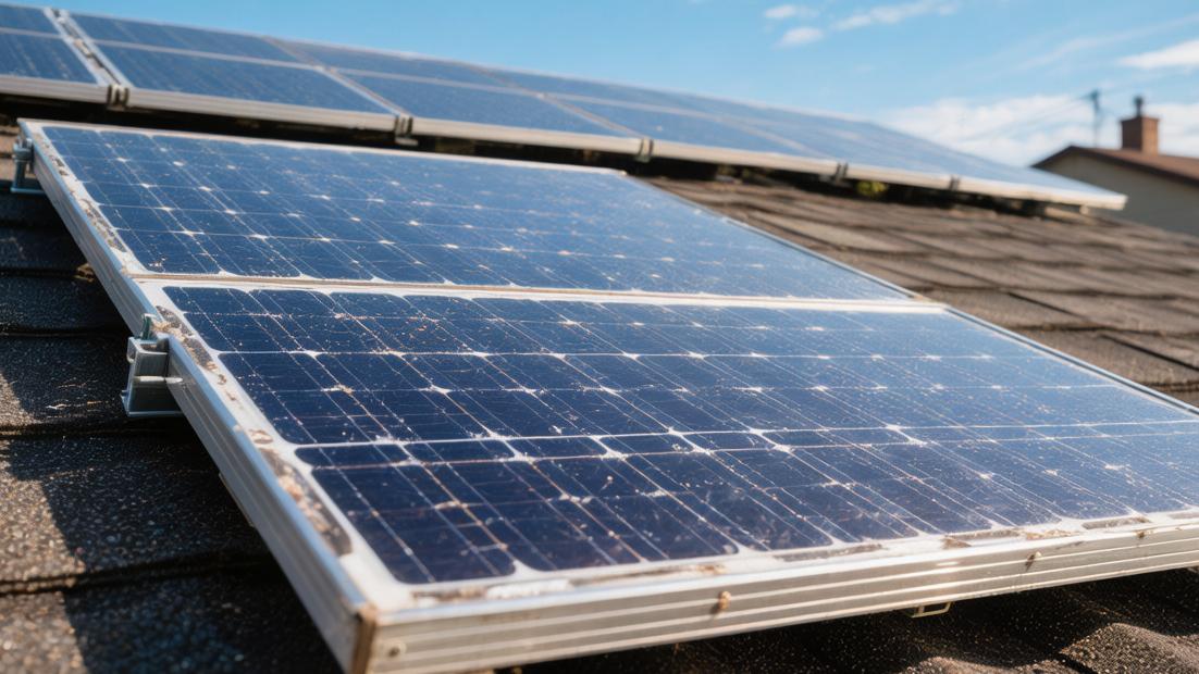
Twenty-five years of all-weather outdoor physical exposure subjects the various polymer material layers surrounding the silicon wafer to varying degrees of transmittance decline and insulation impedance reduction.
The ethylene-vinyl acetate (EVA) high-transparency encapsulation film, tightly bonded beneath the 3.2 mm tempered photovoltaic glass, undergoes irreversible mutation in cross-linking degrees within its polymer chains after accumulating over 50,000 hours of intense ultraviolet radiation.
Visible yellowing occurs on the panel surface, causing the average optical transmittance in the 380 nm to 780 nm visible light spectrum to slowly drop from a high of 91.5% when new to a lower limit of 86%.
The fluorinated composite backsheet (usually a TPT or KPK three-layer structure) with a thickness of only 0.3 mm, bonded at the bottom, faces stresses from 25 years of wind and sand abrasion and thermal expansion/contraction due to day-night temperature differences.
Its absolute water vapor transmission rate increases from 1.5 g to 2.8 g per square meter per day.
Trace moisture infiltration increases the probability of electrochemical corrosion on the silver busbars of the 156.75 mm x 156 mm polycrystalline silicon wafers.
The 6063-T5 anodized aluminum alloy frame fixed around the panel features a 15 μm thick anti-corrosion oxide film.
After 3000 hours of neutral salt spray testing in a 0.05 mol per liter concentration, the oxide layer thickness wears down by at most about 3 μm.
It remains capable of withstanding a front-side static snow load of up to 5400 Pa and a back-side wind pressure tensile strength of 2400 Pa, with a physical fracture probability of less than 0.01%.
The Financial Math
Inside the IP68-rated junction box encapsulated on the back of the solar panel, three Schottky bypass diodes with rated currents of 15A to 20A are typically pressure-welded.
The hardware failure probability due to thermal runaway is only 0.05% over 25 years.
However, the electrolytic capacitors on the mainboard of string inverters, responsible for converting the panel's direct current (DC) into grid-connected alternating current (AC), will inevitably experience physical drying of the electrolyte between the 12th and 15th year after continuous exposure to peak operating temperatures of 105°C.
This leads to a Total Harmonic Distortion (THD) of the output current waveform exceeding the 5% grid connection red line.
When designing a project's financial return on investment (ROI) model for 25 years, the following clear expenditure and revenue figures should be entered into the LCOE (Levelized Cost of Energy) calculation formula:
· The average price for initial system hardware procurement and construction/installation currently remains stable between $2.50 to $2.80 per watt. The upfront total capital expenditure (CAPEX) for a standard 8 kW single-phase system is $20,000 to $22,400.
· The average future replacement cost for string inverters is estimated between $0.12 to $0.15 per watt. Owners must reserve a budget of $960 to $1,200 in their bank accounts for full hardware replacement in the 12th year.
· Based on a regional grid benchmark retail price of $0.14 per kWh, the absolute amount of electricity bills saved for a household in the first year is approximately $1,190. After offsetting data with an annual 3% electricity price inflation rate and a 0.65% power generation degradation rate, the annual saving in the 25th year will unilaterally increase to $1,850.
· After deducting annual maintenance costs of $100 to $150 for high-pressure water gun cleaning and labor costs for cable leakage testing, the system's comprehensive Internal Rate of Return (IRR) can be firmly anchored within a 11.5% to 14.2% range. Owners can achieve 100% full recovery of the hardware investment on a timeline of 6.5 to 7.8 years. The remaining 17+ years of pure power generation will continuously generate positive cash flow returns exceeding $28,000.
Voltage Measurement
Under Standard Test Conditions (STC: solar irradiance 1,000 W/m², atmospheric mass AM1.5), a polycrystalline panel in healthy mid-term operation (years 10 to 15) should not have an overall drop in Open Circuit Voltage (Voc) exceeding 3% of the initial 38.5V nominal value.
Similarly, the Short Circuit Current (Isc) data slide should be controlled within a 5% deviation range based on the factory 9.2A.
When the insulation impedance of a single parallel string shown on the monitoring dashboard drops below 500 kΩ in a morning environment with 85% relative humidity, or when the calculated Fill Factor (FF) plummets below 70%, it indicates that the encapsulated solar cells have already encountered an abnormal increase in Series Resistance (Rs) or a catastrophic decrease in Shunt Resistance (Rsh).
Using industrial drones equipped with thermal imaging cameras for PV matrix cruise scanning during high irradiation periods between 12:00 PM and 2:00 PM, an infrared temperature sensitivity of 0.1°C can keenly capture high-risk hot spot effects on the panel surface.
When a specific 5 cm square area shows a temperature abnormally higher than surrounding areas by 15°C to 20°C, the PN junction reverse leakage current in that physical region will surge exponentially.
This consumes 8% to 10% of the panel's real-time output power for nothing, with local peak temperatures potentially exceeding the 150°C melting point, burning through the EVA backsheet.
Degradation Rate
How Fast is the Power Drop
When photons with wavelengths between 300 nm and 1100 nm penetrate the 3.2 mm thick front ultra-white embossed glass and hit the 180 μm thick P-type polycrystalline silicon layer, the high density of defect states at the grain boundaries captures some of the excited electron-hole pairs.
This leads to an increased recombination rate, resulting in an irreversible physical decay of the output DC power over time.
Under Standard Test Conditions (STC: irradiance 1,000 W/m², cell temperature 25°C, air mass AM1.5), a newly unboxed 280W polycrystalline module typically has a Short Circuit Current (Isc) set at 8.95A and a nominal Open Circuit Voltage (Voc) of 38.8V.
Within the first 300 days of grid-connected operation, the overall output power of the panel experiences its steepest decline. The Light-Induced Degradation (LID) effect causes peak power to evaporate by 2% to 2.5%.
Most physical loss stems from trace amounts of boron and oxygen atoms remaining in the silicon wafer from the crystal pulling process. Under continuous high-intensity ultraviolet irradiation, these combine into irreversible boron-oxygen complexes, causing the minority carrier lifetime to rapidly plummet from an initial 200 μs to below 50 μs.
Over a rated 25-year life cycle, more than 60% of the total LID drop in polycrystalline modules is completed within the first 72 hours of grid connection. The DC input operating voltage shown on the inverter's MPPT (Maximum Power Point Tracking) channel will drop from an average of 32.5V to around 31.8V within three days. In the following eight months, the slope of the data degradation curve gradually flattens, with the median probability distribution of the total power drop in the first year typically fixed at 2.2%.
Annual Degradation
Long-term operation and maintenance statistics from large-scale ground-mounted PV plants and megawatt-level commercial rooftop projects show that the median annual degradation rate of polycrystalline modules from year 2 to year 25 falls on a narrow data point of 0.65%.
In a large sample pool of 10,000 mixed monocrystalline and polycrystalline silicon panels, the variance of the annual average degradation rate for polycrystalline silicon remains at an extremely small level of 0.002, with the standard deviation strictly controlled within a data boundary of 0.05%.
Assuming the actual available peak power at the end of the first year is 97.5% of the nominal power, and decreasing according to an arithmetic progression of 0.65% per year, the theoretical minimum peak power limit for the panel at the 10-year mark is 89.55%. When running at full load until the end of the 20th full natural year, the actual output capacity drops to 83.05%.
When physically disassembling a whole panel into 60 individual 156.75 mm x 156.75 mm polycrystalline silicon cells and measuring at the microscopic level, the Series Resistance (Rs) of each cell increases by an average of 0.005 ohms per year due to the slight electrochemical oxidation of the silver paste busbars.
The shunt resistance (Rsh) slowly drops from 500 ohms at the factory test stage to 350 ohms. The linear deterioration of resistance parameters precisely drives up the ineffective thermal loss within the module.
At 12:00 PM in summer, when the maximum air temperature reaches 40°C, the peak temperature of the polymer backsheet on the rear of the panel can climb to the 65°C to 70°C range.
Performing regression analysis based on the fixed power temperature coefficient of -0.41%/°C for polycrystalline silicon, the thermal degradation from high temperatures, superimposed with long-term linear hardware degradation, will cause the instantaneous high-load output power of a nominal 280W panel to fall below the 195W test lower limit in its 15th summer.
Calculating Errors
Placing batch-sampled test panels into a high-low temperature alternating environment test chamber with an internal volume of 3 cubic meters, the cycle temperature is set to fluctuate drastically between -40°C and 85°C.
Simultaneously, the relative humidity in the chamber is increased and maintained at a high level of 85%, applying a continuous system-level reverse bias voltage of 1000 V to 1500 V to the positive and negative poles.
After undergoing 192 hours of high-intensity Potential-Induced Degradation (PID) limit testing, large amounts of active sodium ions in the surface embossed glass migrate rapidly toward the polycrystalline silicon cell surface under the action of the polarized high-voltage electric field.
This severely damages the silicon nitride anti-reflection film and passivation isolation layer on the surface.
Flash illumination testing on the instrument side shows a staggering single-time drop rate of 3% to 5% in the panel's front-end total output power.
Because the purity of silicon material refined in each batch by upstream factories has minute concentration deviations at the parts-per-million (ppm) level, the actual measured input power of 100 sampled inverter strings within a physical block of a 5 MW total installed capacity will show a data dispersion of 0.15% on a normal distribution curve.
When building actuarial models for a project's 25-year Internal Rate of Return (IRR) and Net Present Value (NPV), power station asset owners must fully enter a 2.5% degradation base for the first year and a 0.7% degradation upper limit for subsequent years into the calculation tables.
They must also mandatorily deduct 2% to 3% for line insulation aging loss costs in the year 15 cash flow budget column.
As long as the open-circuit voltage of the overall DC string does not drop significantly below the 200V startup threshold set by the inverter, the entire AC/DC conversion system can maintain a full-load conversion accuracy of over 98%, continuously converting a steady stream of DC power into standard AC power with a frequency of 50 Hz or 60 Hz and voltage fluctuations below 3% to be sent to the regional main grid.
Measuring Data
A string-type three-phase AC inverter with a rated output power of 50 kW is connected to a DC-side rated hardware load of 55 kWp polycrystalline modules under clear, cloudless weather with a peak solar irradiance of 800 W/m².
In the 5th year of all-weather grid-connected operation, the theoretical maximum instantaneous DC power generation of this massive array—composed of exactly 200 individual units with a rated power of 275 W—will completely recede from 53.6 kW during initial testing to 51.4 kW.
The thermal dissipation efficiency loss during the DC-to-AC conversion process, combined with the inherent physical voltage drop of hundreds of meters of copper core cables, will strictly limit the active power output at the grid-connected meter end to a physical upper limit of 49.2 kW.
Field O&M engineers use an industrial-grade four-quadrant power analyzer with 0.5-level measurement accuracy.
The median voltage sample collected at high frequency at the inverter MC4 input terminal stays at 620V, which is 12V lower than the initial record during the first year of engineering grid-connection acceptance.
The average operating current of a single string measured by a Hall current probe is 8.3 A. The local leakage current generated in a series circuit of 20 panels is strictly limited by the Residual Current Monitoring Unit (RCMU) inside the frequency converter to below the 30 mA safety trip red line.
Accumulating the total active grid-connected electricity over a 24-hour cycle using calculus, it can be concluded that the variance of the single-day absolute power generation in the 5th year of service has expanded from 1.5 at the time of system construction to 1.8.
This large data sample dispersion fully demonstrates the performance of polycrystalline panels installed in different physical orientations.
Facing multiple natural environmental stresses such as irregular local dust shading, tens of thousands of hours of cumulative UV radiation penetration, and wind/sand physical abrasion, not only has the overall output power mean shifted downward, but the positive correlation of power generation between individual panels within the same matrix is also separating at a small annual coefficient of 0.02.
Factors Influencing Durability
Sensitive to Heat and Cold
Polycrystalline panels operate outdoors in all weather conditions, and drastic fluctuations in ambient temperature exert continuous physical expansion and contraction pressure on the 156.75 mm square silicon wafers inside.
On the 25°C baseline set by Standard Test Conditions (STC), for every 1°C increase, the module's output power accurately decreases according to a temperature coefficient of -0.41%.
Sampling statistics from the Arizona desert in North America show that when absolute summer noon temperatures climb to 45°C, the actual peak temperature on the panel surface can easily surpass 65°C.
Calculating the power loss regression equation at this time, the instantaneous power of a polycrystalline module with a nominal output of 300W will plummet to 250.8W, with a single power fluctuation amplitude exceeding 16%.
In winter, nighttime temperatures often drop to -20°C. High-frequency cyclic thermal stress from -20°C to 65°C generates microscopic shear stress at the solder joints between the silicon wafer and the copper-clad aluminum ribbon.
X-ray scans of 1000 panels operating for over 10 years show a median probability distribution of ribbon desoldering reaching 4.5%.
To quantify the damage caused by thermal stress, laboratories typically place panels in a high-temperature and high-humidity environmental chamber between -40°C and 85°C for 200 thermal cycles (TC200) limit testing.
The dispersion of the measured Short Circuit Current (Isc) before and after testing expands by 0.15, and the mean Fill Factor (FF) produces a negative deviation of 2%, significantly driving up the LCOE budget costs.
Vulnerable to Wind and Snow
The mechanical load pressure from wind speed and snowfall in nature acts physically on the 3.2 mm thick low-iron tempered embossed glass on the front of the panel.
According to the International Electrotechnical Commission (IEC) physical strength measurement standards, a qualified polycrystalline panel must withstand a static snow load of 5400 Pa on the front and a dynamic wind load of 2400 Pa on the back.
In coastal hurricane-prone areas, when instantaneous wind speeds exceed 35 m/s, the tensile strength borne by the aluminum alloy frame reaches 70% of its yield limit.
If the high-frequency vibration amplitude of the panel caused by wind exceeds a physical range of 3 mm up and down the vertical plane, the 180 μm thick polycrystalline silicon cells are highly susceptible to irreversible micro-cracks.
· In hail impact tests, when a solid ice ball with a diameter of 25 mm and a mass of approximately 7.5 g hits the glass surface vertically at a gravitational acceleration of 23 m/s, the pass rate for intact glass must remain within a 99.9% confidence interval.
· Detection sample libraries from infrared EL imaging instruments show that 0.1 mm cross-type micro-cracks widely distributed on silicon wafers cause a surge in the Series Resistance (Rs) of local cells. This triggers abnormal heating, with the local temperature of hot spot areas 15°C to 20°C higher than the average.
· Bringing the grid-connected data of panels containing micro-cracks into the LCOE financial model, the annual power generation revenue per panel loses about $1.5 due to increased leakage current. This drives up the entire system's operating costs and lowers the long-term Internal Rate of Return (IRR) percentage.
Material Aging
The sandwich encapsulation structure of polycrystalline panels undergoes significant physical degradation in the transmittance and insulation of its polymer material layers after being bombarded by tens of thousands of hours of intense ultraviolet (UV) radiation.
The ethylene-vinyl acetate (EVA) film wrapping the front and back of the cells undergoes chemical changes in its internal cross-linking after accumulating more than 15 kWh/m² of UVA and UVB band ultraviolet radiation, resulting in visible yellowing.
In spectral transmittance tests with an integrating sphere in the lab, yellowing causes the photon penetration rate in the 380 nm to 780 nm visible light band to drop by 2.5% to 3.2%.
The sharp percentage reduction in photons reaching the P-N junction results in a leftward shift of the average Maximum Power Point Current (Imp) by 0.2A in the output data.
The fluoropolymer backsheet located at the bottom of the panel, usually 0.3 mm to 0.35 mm thick, becomes brittle and undergoes pulverization after long-term exposure to air.
Placing a 15-year-old aged backsheet slice into a universal material testing machine, the statistical standard deviation of its physical elongation at break plummets from 150% at the factory to less than 50%.
Moisture and Salt Mist
Relative humidity in the air and the concentration of sodium chloride dissolved in water droplets are high-risk natural factors that cause system insulation leakage and trigger Potential-Induced Degradation (PID).
In high salt-mist areas less than 5 km from the coastline, the peak concentration of chloride ions suspended per cubic meter of air can reach 300 mg.
When environmental relative humidity (RH) fluctuates in the high range of 80% to 90% for a long time, water vapor molecules slowly penetrate through the polymer gaps of the backsheet into the internal cavity of the panel at a rate of 1.5 g to 2.5 g per square meter per day.
Moisture reacts with trace amounts of acetic acid decomposed from the EVA film. The resulting acidic environment causes severe corrosion and breakage of the silver busbars, which are only 1.5 mm wide, on the polycrystalline silicon wafers.
· Under the action of a 1000 V or 1500 V high-voltage bias electric field at the DC end of the system, a large amount of sodium ions in the surface embossed glass migrate toward the silicon nitride anti-reflection film on the cell surface.
· Positively charged sodium ions attract and neutralize a large number of minority carrier electrons in the P-type polycrystalline silicon substrate, leading to widespread local short-circuit phenomena. Shunt Resistance (Rsh) readings on test instruments plummet from a healthy 500 ohms to less than 50 ohms.
· In string circuits experiencing severe PID effects, the overall system conversion efficiency drops by more than 10% in just six months. On the voltage-current (I-V) curve tracked by the inverter's MPPT, the accuracy and following precision of the Maximum Power Point (Pmpp) will yield a system error of more than 5%. The monthly actual grid-connected electricity loss converts to $25 to $30 in local currency.