Why Are 500-Watt Solar Panels a Smart Choice | Higher Output, Fewer Panels, Better Efficiency
A 500W solar panel is a highly cost-effective and practical choice. Its core strengths are clear: higher output, less space required, and better efficiency.
Compared with a traditional 300W panel, a 500W panel typically delivers a conversion efficiency of over 21%, with significantly higher output per module.
For example, to build a standard 5 kW residential solar system, you only need 10 500 W panels, whereas a conventional setup would require about 17 panels.
Higher Output
Under standard laboratory test conditions of 1,000 W/m² irradiance and a cell temperature of 25°C, a single 500 W solar panel produces a fixed output of 0.5 kWh per hour.
In a dry region at 35° north latitude with around 1,800 annual sunshine hours, a single 500W panel can generate 2.65 to 2.75 kWh per day during 5.5 hours of effective peak sunlight.
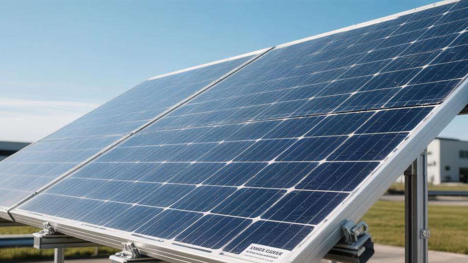
With physical dimensions of 2.22 meters long and 1.13 meters wide, one panel occupies 2.51 square meters, delivering a power density of 199.2W per square meter.
Older 400W panels typically remain at around 185W per square meter, so a 500W panel increases generation efficiency per unit area by 7.6%.
To handle a 13.5A short-circuit current and 45.8V open-circuit voltage, a 500W panel is built with 144 half-cut cells, each measuring 182 mm × 91 mm, reducing internal resistance by around 12% and keeping front-side conversion efficiency stable within the 21.5% to 22.3% range.
· When summer temperatures climb to 38°C, the surface of a dark-colored panel can quickly reach 65°C. At that point, the 500 W panel's -0.30%/°C temperature coefficient comes into play.
· Compared with the standard baseline of 25°C, a 40°C temperature difference results in a 12% thermal loss, reducing actual output by 60 W, yet the panel can still maintain a steady output of 440 W.
· An older 400W panel with a -0.35%/C temperature coefficient would suffer a 14% thermal loss under the same 65°C conditions, with output dropping sharply to 344W.
· Under NOCT conditions—that is, 800 W/m² irradiance, 20°C ambient temperature, and 1 m/s wind speed—a 500 W panel can sustain an output of 378 W to 385 W.
Low-Light Performance
From 6:30 a.m. to 8:00 a.m., and again from 4:30 p.m. to 6:00 p.m., the sun sits at a lower angle, and ambient irradiance usually ranges from 150 W/m² to 350 W/m².
Most 500W panels use a dense busbar design ranging from 9BB to 16BB, which shortens the current transmission path across the cells by 2.5 mm to 3.8 mm and reduces series resistance by 15%.
At a low irradiance level of 200 W/m², the relative conversion efficiency of a 500 W panel falls by only 2.2% to 2.8%, allowing each panel to maintain a real-time output of 92 W to 98 W even in weak light.
Under the same 200W/m² light intensity, a 400W panel sees its efficiency drop by 5.5% to 6.5%, leaving real-time output at only 62W to 68W.
During the combined 3-hour low-light windows in the morning and evening, a single 500W panel can generate an extra 0.15 to 0.25 kWh per day. In a 10 kW array made up of 20 500 W panels, that means an additional 3 to 5 kWh per day captured from weak-light conditions alone.
Over 12 months, the total additional generation reaches 1,095 to 1,825 kWh. At an average electricity price of $0.15 per kWh, that low-light gain translates into $164 to $273 per year.
Degradation Data
Total lifetime energy yield depends heavily on two hard performance indicators: first-year light-induced degradation (LID) and the subsequent annual linear degradation rate.
A 500W panel built with N-type phosphorus-doped silicon wafers can deliver 6.8% to 8.5% more cumulative electricity over a 9,125-day operating life than older-generation products with a 0.55% annual degradation rate.
· Over the first 8,760 hours—the first year—initial power degradation is kept below 1.0%, so at the start of month 13, the rated output still stands at 495W.
· By comparison, a traditional P-type 400W panel typically experiences 2.0% to 2.5% degradation in the first year, leaving rated output down at around 390W after one year of operation.
· From month 24 to month 300, the 500W panel degrades linearly at a fixed rate of 0.40% every 12 months, which equals a loss of 2W of rated power per year.
· By month 120—its 10th year of service—the panel can still deliver 477W, retaining 95.4% of its original capacity.
· By month 300—the 25th year—final output remains at 447W, with a system retention rate of 89.4%.
Fewer Panels
Saving Space
To build a 20 kW commercial flat-roof solar array using 400 W panels with a conversion efficiency of 19.5%, each panel measuring 1.76 meters by 1.04 meters, the physical coverage per panel is 1.83 square meters.
To reach the full 20 kW installed capacity, the system would require 50 panels, resulting in a total panel surface area of 91.50 square meters.
Each panel also requires a 20 mm thermal expansion gap around its perimeter. Across 50 panels, those gaps add up to about 1.45 square meters, expanding the total system footprint to 92.95 square meters.
If you switch to a 500W panel with a 21.5% conversion rate, each module measures 2.09 meters by 1.04 meters, covering 2.17 square meters.
Because of the higher output per module, the total panel count drops to 40, reducing the total panel surface area to 86.80 square meters. Gap area also shrinks to 1.16 square meters.
As a result, the actual rooftop projection area of a fully loaded 20 kW system drops from 92.95 square meters to 87.96 square meters.
That 4.99-square-meter reduction frees up 5.3% more usable roof space, leaving room for future HVAC equipment or a standard 600 mm-wide maintenance walkway.
Using Less Metal
Under a conventional horizontal layout, 50 400W panels arranged in 5 rows of 10 require 104 meters of aluminum mounting rails. Based on a 6005-T5 aluminum rail density of 1.2 kg per meter, the total rail weight comes to 124.8 kg.
With 40 500W panels arranged in 4 rows of 10, total rail demand drops to 83.2 meters, and the metal weight falls to 99.8 kg.
According to the engineering standard of installing one L-foot roof mounting bracket every 1.2 meters, the 104 meters of rail used for a 50-panel system requires 87 mounting bases.
The 83.2 meters of rail in the 40-panel system require only 70 mounting bases.
On the procurement side, cutting 20.8 meters of rail at $5.5 per meter reduces material cost by $114.4.
Eliminating 17 stainless steel bases at $3.2 each saves another $54.4.
Together, the total procurement cost for metal accessories drops by 18.5%.
Reducing Roof Leak Risk
Each mounting base requires M8 stainless steel expansion bolts or self-tapping screws with a length of 80 mm to penetrate the TPO waterproof membrane or the asphalt shingle layer.
With 87 mounting bases, the roof ends up with 87 potential moisture entry points.
Reducing the total number of drilled holes to 70 lowers the density of penetration points by 19.5% within the same physical area.
Using a binomial probability model based on a baseline leakage probability of 0.15% per bolt hole after 120 months of UV exposure and cyclic thermal expansion and contraction between -20°C and 60°C, a roof with 87 holes has a 12.2% chance of developing at least one leak over that period.
A system with 70 holes, under the same conditions, lowers that risk to 9.9%.
By eliminating 17 mounting holes, the installation crew also reduces polyurethane industrial sealant usage by 425 mL.
When installers tighten M8 bolts using a power wrench set to 18 N·m, removing those 17 holes also eliminates 34 repeated tightening actions, reduces tool wear, and cuts total installation time by about 45 minutes.
Better Efficiency
A Better Silicon Base
Inside a laboratory test chamber held at 25°C, the upper limit of solar conversion efficiency is determined by the physical doping process used in the semiconductor material the moment photons strike the silicon surface.
Earlier, 400W-class panels widely used boron-doped P-type monocrystalline silicon wafers, with mass-production conversion efficiency typically topping out at 20.5% to 21.2%.
Most mainstream 500W panel production lines now use phosphorus-doped N-type TOPCon wafers at the cell level. With an ultra-thin silicon oxide tunneling layer measuring just 1.5 to 2.0 nanometers, electron-hole recombination is reduced by about 60%.
Based on the 182 mm × 182 mm M10 large-format wafer standard, conversion efficiency per wafer is pushed up to a high-performance range of 22.5% to 23.2%.
When exposed to standard 1,000 W/m² sunlight on the day it leaves the factory, an N-type 500 W panel keeps its first-year LID tightly controlled within 0.8% to 1.0%.
By contrast, older P-type panels exposed to strong outdoor UV radiation over the first 360 hours of operation see their LID rise quickly and eventually stabilize at a much higher loss level of 2.0% to 2.5%.
After enduring as long as 300 months—a full 25 years—of outdoor exposure to harsh climate conditions, and assuming a steady linear power degradation rate of 0.40% per year, an N-type solar panel originally rated at 500W can still continuously deliver 446W of DC output to the inverter at the end of its service life.
That is 46W above the industry minimum end-of-life standard of 80% capacity, which in this case would be 400W.
Cutting the Cells in Half
Improvements in high-precision cutting technology have fundamentally changed the way current flows and heat is distributed inside a solar panel measuring 2.22 meters by 1.13 meters.
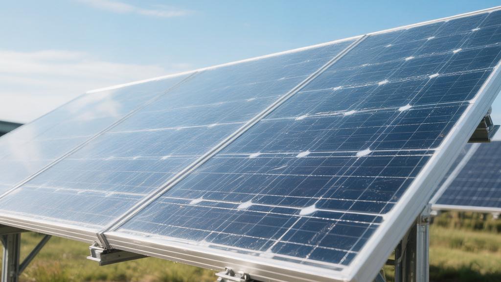
On lossless cutting lines, infrared lasers follow micron-level cutting paths to split 144 full 182 mm square monocrystalline cells horizontally down the middle. During lamination, they are reassembled into two perfectly symmetrical, fully parallel strings of 72 half-cells each.
In a fully closed-loop electrical system, the maximum operating current in a single path is physically reduced from 13.5A in full-cell designs to a much safer 6.75A.
According to the Joule heating formula in electrical engineering—where heat generation equals the square of the current multiplied by conductor resistance, P = I²R—a precise 50% reduction in current cuts resistive heat loss in the metallic grid lines inside the cells by 75%.
During windless summer noon conditions with ambient temperature reaching 35°C, half-cut cell architecture can suppress and cool the panel's rear-side operating temperature from the nominal 45°C NOCT level down to a relatively lower 43°C.
If the lower half of the panel is unexpectedly shaded by a fallen leaf measuring 15 cm by 10 cm, the isolated upper half—its 72-cell independent string—is not dragged down by voltage loss in the 1000V series system. It can still maintain 50% of the panel's designed rated output, meaning a stable 250W of power delivery.
This avoids the extreme failure mode seen in early full-cell panels, where even minor localized shading could trigger a hot-spot effect and cause the entire module's output to collapse instantly to 0W.
Denser Silver Gridlines
The density of the microscopic conductive network that collects and exports free electrons ultimately determines the current-handling ceiling of a 500W-class panel under 1,000W/m² peak irradiance.
Panel design has evolved from the earlier 5BB architecture to much denser 11BB and even 16BB layouts, more than doubling the number of conductive silver lines on the front and rear surfaces of each silicon cell.
The physical spacing between busbars has been narrowed sharply from 3.1 mm in the full-cell era to just 1.2 mm, cutting the average effective travel distance of photo-generated electrons by more than 50% before they reach the metal collection points.
During the screen-printing stage, manufacturers have also replaced traditional flat rolled tinned copper ribbons with highly reflective round solder ribbons having a cross-sectional diameter of only 0.25 mm to 0.32 mm, fully addressing the shading problem caused by wider conductors blocking photons from reaching deeper regions of the silicon.
With their 360-degree optical curved profile, these round metallic conductors can redirect 40% to 45% of visible light that would otherwise be lost to skyward diffuse reflection. At carefully controlled geometric angles, that light is refracted back into the inner surface of the 2.0 mm high-transmission anti-glare tempered glass, where it can then be reabsorbed by the silicon semiconductor layer below.
Thanks to this microscopic optical path optimization, the panel's all-day real-world generation efficiency increases by an additional 0.3% to 0.5% on top of its original performance.