How Do You Implement a Solar Energy System in Aquaculture | 3 Steps
First, assess the power demand, such as aerators (approx. 1–3 kW) and water pump loads, and design the photovoltaic capacity based on solar conditions (annual average 4–5 hours of peak sunshine);
Second, select equipment, configuring photovoltaic panels (e.g., a 10 kW system requires about 30–40 modules) and energy storage batteries to ensure stable power supply at night;
Finally, perform installation and maintenance, optimizing the tilt angle (approx. 30°) and regularly cleaning the modules, which can reduce electricity costs by over 30% and improve aquaculture efficiency and sustainability.
Assess Energy Needs and Requirements
Calculating Total Electricity Consumption
Review the electricity bills from the past 36 months and list monthly power usage exceeding 500 kWh separately in a 12-column spreadsheet.
A 10-hectare tilapia farm, during the summer when temperatures reach 32°C, typically sees its monthly electricity consumption soar to 8500 kWh.
Identify months where power usage fluctuates by more than 20% and mark them as high-frequency operation periods with a load rate reaching 85%.
Record the readings on the main meter continuously 24 hours a day for 14 consecutive days to derive a daily baseline power consumption with a deviation rate lower than 3%.
Allocate 30% of the total daytime power consumption to the 3 kW water pump, 60% to the 4 kW aerator, and leave the remaining 10% for the 50 W night lighting strips.
· Measure the actual operating voltage of the 3-phase power supply lines at 6 AM and 2 PM, and record areas where the single-phase voltage drop exceeds 15 V in Memorandum No. 2.
· Record the specific minutes when the dissolved oxygen concentration in the water drops below 3.5 mg/L, and identify the corresponding 60 A current surge phenomenon when the aerator reaches 100% full-load operation.
· Verify the peak electricity pricing rule of $0.25 per kWh and control the power consumption ratio from 8 AM to 8 PM (totaling 12 hours) within 45% of the daily total consumption.
Inspecting Machinery
Verify the metal nameplate parameters of all aquatic equipment around the pond, recording 24 sets of power data ranging from 0.75 kW to 5.5 kW.
An impeller aerator equipped with a 2 HP motor operating at 220 V will maintain an actual working current between 8.5 A and 9.2 A.
When 15 devices of the same specification are switched on simultaneously, the instantaneous starting current will soar to 3.5 times the rated current, subjecting the local grid to a 75 kW surge lasting 1.5 seconds.
Fill in the 4th row of the table with the rated flow rate of 400 m³/h for the water pump, then multiply by 18 hours of daily operation to obtain the total water exchange volume of 7,200 m³ and the corresponding power consumption value.
For every 1°C rise in water temperature, the dissolved oxygen saturation of the water body will decrease by 2.5%, forcing a 3 kW aeration device to run for an extra 45 minutes daily to compensate for the 0.8 mg/L oxygen gap.
· Use a digital clamp meter to clamp the copper core main cable with a cross-sectional area of 10 mm², and read the real-time current fluctuation curve accurate to 0.1 A every 5 minutes.
· Convert the 12-minute working periods required for 8 automatic feeders to spray 50 kg of pellet feed each time into a single absolute power consumption of 0.4 kWh.
· Calculate the 4.2% line loss rate caused by the 150-meter-long old aluminum core cable, translated into an annual loss of 1850 kWh of wasted electricity expenditure.
Measuring Solar Irradiance
Retrieve the shortwave solar radiation dataset with 1-hour resolution from the local weather station for the past 10 years, filtering out 78 rainy days with peak sunshine hours less than 3.5 hours.
At an aquaculture base located at 35° North or South latitude, the total solar radiation received per square meter of water surface fluctuates annually between 1450 kWh and 1750 kWh.
Set a full-load effective power generation period of 5.2 hours per day for spring and autumn, and reserve a 20% production reduction buffer for the winter period when there is only 2.8 hours of light per day.
When the surface temperature of the PV panel rises to 45°C, the photoelectric conversion efficiency will drop from 21.5% in the product manual to 19.8%.
Incorporate the 1.7% temperature-related negative pressure drop coefficient fully into the 25-year system life-cycle power generation prediction model.
· Fix a pyranometer to the top of a steel pipe bracket 1.5 meters above the water surface to capture instantaneous irradiance values ranging from 200 W/m² to 1050 W/m² every 15 minutes.
· Measure the shadow area cast by tree canopies exceeding 15 meters in height from 8 AM to 4 PM, ensuring that the canopy-shaded area accounts for less than 4.5% of the total water surface area.
· Measure the early morning dense fog phenomenon with 50-meter visibility produced when the relative humidity of the water surface reaches 85%, and subtract approximately 12.4% of light scattering attenuation from 7 AM to 9 AM from the calculation table.
Select the Right Solar Energy Modules
Selecting Panels
Focus on N-type TOPCon bifacial double-glass modules with a nominal power range of 580 W to 620 W.
The physical dimensions of these modules are typically 2,278 mm long and 1,134 mm wide, with top and bottom layers each covered by 2.0 mm thick high-transmittance semi-tempered glass.
Above brackish or seawater aquaculture ponds with salinity reaching 30‰, the silicone sealant between the glass and the aluminum alloy frame needs to pass the Level 6 salt spray corrosion test and a 5% ammonia exposure test.
The water surface produces refraction and wave reflections of sunlight; the transparent backsheet of bifacial modules can absorb water surface reflections, pulling the overall power generation per square meter up by 8% to 12%.
Strictly limit the first-year photoelectric conversion degradation rate in the procurement contract to within 1.0%, and require that the annual linear degradation rate from year 2 to year 25 does not cross the red line of 0.4%.
The temperature coefficient of N-type silicon wafers is stable at -0.29%/°C. When the surface temperature of an unshaded PV panel in summer noon soars to 65°C, its actual power loss will result in 18 W less power output compared to traditional P-type modules.
Require the supplier to provide a 15-year product material warranty, along with a mechanical strength verification report from a third-party testing agency showing resistance to a 2400 Pa wind load and a 5400 Pa snow load.
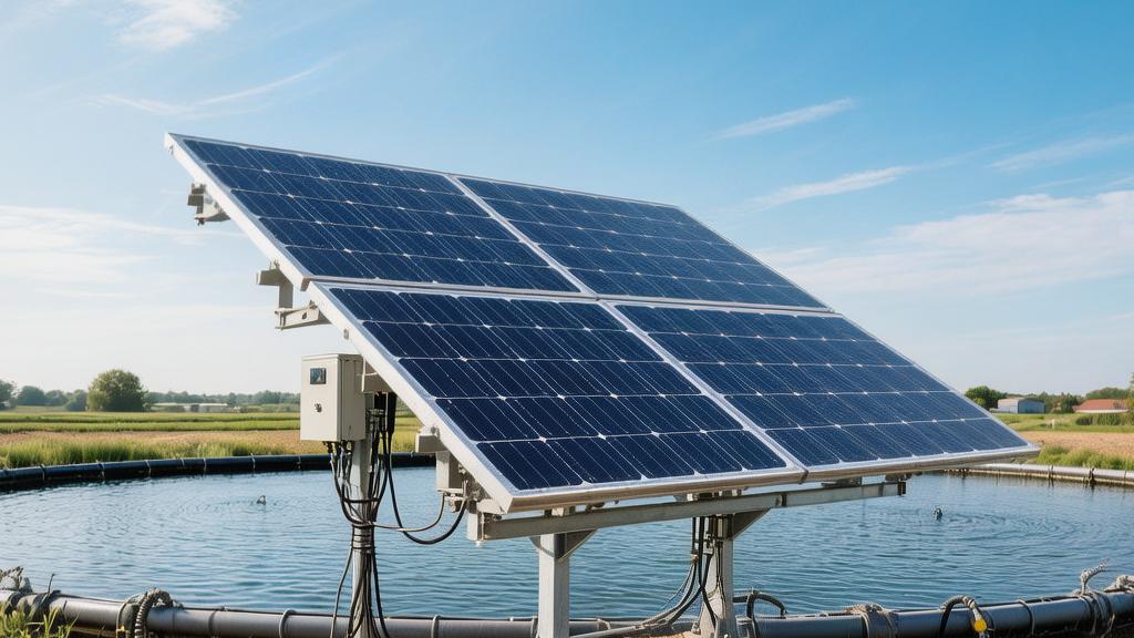
Determining Floats
Discard carbon steel metallic materials which have a high probability of rusting, and adopt High-Density Polyethylene (HDPE) with a density falling in the range of 0.94 g/cm³ to 0.96 g/cm³ as the base material for the floating platform.
During the extrusion process, incorporate anti-UV carbon black into the raw material at a precise ratio of 2.5% to 3.0% to delay plastic aging under 10 hours of daily intense light, ensuring the physical yield strength of the float system does not decrease by more than 15% over 25 years.
Utilize a blow-molding integrated molding process to uniformly control the pipe wall thickness between 4.5 mm and 5.2 mm, ensuring that the dimensional deformation rate remains below 1.5% under extreme temperature cycles from -20°C to +85°C.
A single main float responsible for carrying one 550 W PV panel needs to provide over 150 kg of absolute buoyancy. Combined with aisle floats with a width of 0.5 m, they assemble into a continuous aquatic base with a load-bearing capacity of 250 kg/m².
Arrange polyester mooring ropes with a tensile strength exceeding 30 kN underwater around the float array to counteract the massive thrust generated by 35 m/s wind speeds on the entire water array, preventing the overall offset from exceeding the set tolerance radius of 1.2 m.
Buying Inverters
Mount string inverters with IP66-rated dust and waterproof enclosures on galvanized steel brackets at least 1.8 m above the historical maximum water level.
The area ratio of the aluminum alloy die-cast heat sink fins on the back of the enclosure should reach 65% of the total machine surface area, ensuring the machine dissipates heat via natural convection in a water surface environment where relative humidity stays near 98%. Resolutely avoid built-in cooling fans that are easily damaged by water vapor short circuits.
Regarding financial indicators for conversion efficiency, look for pure sine wave output models with a nominal peak reaching 98.7% and a European weighted efficiency of no less than 98.3%.
Equipment Parameter Indicator | Lower Limit Value | Upper Limit Value | Tolerance Range |
MPPT Voltage Tracking Range | 200 V | 1000 V | ±15 V |
Full-load Operating Ambient Temp | -25°C | 45°C | ±2°C |
Total Harmonic Distortion (THD) | 0.5% | 2.9% | ±0.1% |
DC Input Overload Rate | 130% | 150% | ±5% |
AC Output Rated Current | 144 A | 160 A | ±2 A |
Track the panel open-circuit voltage change curve when the sun rises in the morning, requiring the inverter to immediately wake up and start the grid-connected generation program when the DC side voltage reaches 200 V, forcibly extending the daily effective working time by 45 minutes.
The machine must integrate a DC Arc Fault Circuit Interrupter (AFCI) with a response accuracy of 0.5 seconds. Once the current transformer detects high-frequency distortion in the current waveform, it instantly cuts off the connection circuit.
Set the maximum number of input strings for each 100 kW inverter to 20, diversifying the risk of a localized 20% power drop caused by single panels being shaded by water bird droppings.
Install and Integrate the System
Installing Pipe Piles
The construction team drives a flat-bottom piling boat with a full-load displacement of 15 tons into the 4000-square-meter tilapia pond.
The hydraulic pile driver drill bit, at a speed of 35 rpm, presses prestressed high-strength concrete pipe piles with an outer diameter of 300 mm into the 4.5-meter silt layer underwater.
Set the center spacing between adjacent pipe piles at 5.2 m, and control the verticality error of the 120 foundation support columns for the entire water array within 0.3 degrees.
A clearance height of 1.8 m above the historical maximum water level is reserved at the top of the pipe piles, providing sufficient buffer space for water level rises caused by 250 mm of daily rainfall during the spring flood season.
Install hot-dip galvanized steel flanges with a thickness of 8 mm at the top of the concrete pipe piles, using M16 high-strength bolts with a tensile strength of 800 MPa to lock the aluminum alloy crossbeams with a tilt angle of 22 degrees above.
When withstanding the ultimate pulling force of gust wind speeds reaching 38 m/s, the pull-out resistance test data of a single pipe pile must stay firmly at the 45 kN mark, keeping the deformation rate of the 320 PV panels above (each weighing 28.5 kg) below 1.2%.
Divers descend to the bottom area at a water depth of 2.5 m, spending 45 minutes checking whether there are discarded concrete blocks within a 60 cm radius of each pipe pile that could cause a differential settlement exceeding 15 mm.
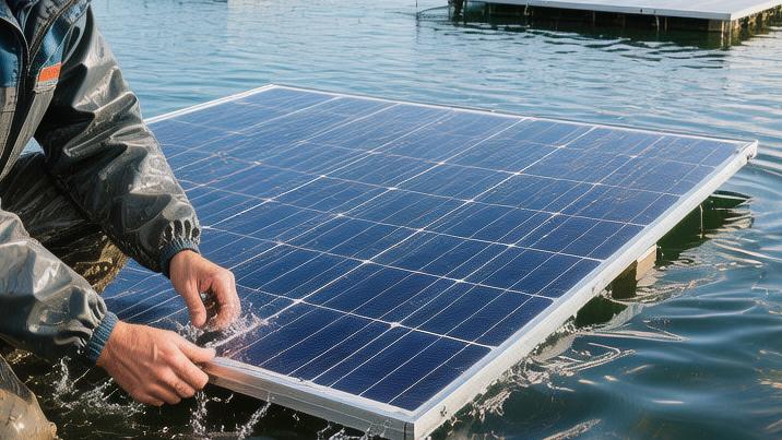
Laying Floats
Abandon rigid metal brackets and use 3500 HDPE main floats to piece together a flexible power generation platform covering 2,200 square meters on the water surface.
Workers push individual floats (1,150 mm long, 750 mm wide, and 400 mm high) into the water, with every 100 floats assembled costing 2.5 man-hours.
Adjacent floats are connected via polypropylene engineering plastic pin shafts with a diameter of 22 mm, narrowing the overall heave amplitude of the array to within 15 cm when wave heights reach 0.6 m.
Leave a 1.5-meter wide maintenance aisle in the center of the float array to carry the mobile weight of maintenance personnel plus toolboxes, totaling 180 kg.
The tugboat drags the assembled 500 kW float modules to the center of the pond, slowly adjusting the orientation to a 180-degree azimuth toward the true south at a speed of 0.5 m/s.
Use 12 ultra-high molecular weight polyethylene ropes with a diameter of 28 mm to fix the four corners of the floats to concrete anchor blocks on the shore, setting the initial pretension of the ropes at 1500 N to counteract the 12% horizontal drift deviation caused by a reservoir current speed of 0.8 m/s.
Adjust the length of the mooring cables to stretch elastically between 15 m and 22 m to accommodate the seasonal water level drop of up to 3.5 m between the dry and wet seasons of the reservoir.
Connecting Wiring
Electricians wearing insulated gloves series-connect every 20 modules with a rated power of 550 W into an independent circuit, outputting a DC voltage as high as 850 V.
Photovoltaic-specific DC cables with a cross-sectional area of 6 mm² extend along the 50 mm wide cable troughs reserved in the floats, with the total laying length reaching 1850 m.
Hammer in an anti-UV nylon tie every 1.2 m to control the surface temperature of the cable insulation layer within a safety threshold of 55°C after 12 hours of sun exposure.
16 sets of DC series cables are connected to a combiner box with an IP65-rated enclosure. A 15 A DC fuse will cut the physical connection within 0.05 seconds if it encounters a reverse current exceeding 20 A.
Multimeter probes contact the positive and negative copper bars of the combiner box to read open-circuit voltage with an accuracy of 0.1 V, identifying faulty strings with a difference exceeding 15 V.
Insert the three-core copper cable at the AC output end, with a cross-sectional area of 120 mm², into a corrugated pipe with an outer diameter of 110 mm. Bury it 0.8 m deep below the permafrost layer, keeping the 380 V voltage drop within a 200-meter transmission distance firmly below the 2.5% limit.
Use a megohmmeter to apply a test voltage of 1000 V to the cable jacket for 60 seconds; the needle should stay steadily on an insulation resistance reading exceeding 500 MΩ.