Why Choose Thin-Film Solar Panels for Mobile Installations | 3 Reasons
First is the extreme lightness and thinness; its weight is only 20% of traditional rigid panels (approximately 2.5 kg/㎡), which can significantly reduce rooftop load-bearing requirements and wind resistance.
Second is the high flexibility; the panels can bend up to a maximum of 30 degrees, allowing them to perfectly fit curved vehicle body surfaces without the need for drilling or installing complex metal brackets.
Finally, there is superior low-light performance; thin-film panels using materials such as CIGS have extremely strong anti-shading capabilities.
Even under common outdoor conditions like tree shade or cloudy weather, the decay in power generation efficiency is far lower than that of traditional monocrystalline silicon panels, providing you with more stable off-grid power security.
Curved Surfaces
Bending Capability
Traditional crystalline silicon solar panels consist of tempered glass, silicon wafers, and an aluminum alloy frame with a thickness usually between 35 mm to 40 mm.
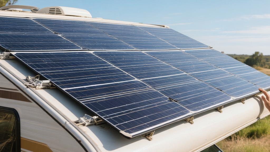
The roofs of RVs, campervans, and yachts are commonly designed with curved, streamlined shapes for considerations of aerodynamics, structural strength, and drainage.
The curvature radius of a standard Class B RV roof is typically between 1.5 meters to 3 meters.
Thin-film solar panels use a polymer substrate instead of heavy tempered glass.
Taking Copper Indium Gallium Selenide (CIGS) thin-film cells as an example, the photoelectric conversion material layer is only a few microns thick, encapsulated in ETFE (Ethylene Tetrafluoroethylene) or PET film.
These physical characteristics give thin-film modules extreme flexibility, allowing for a bending range of up to 30 degrees, with a minimum bending radius as small as 20 cm.
· When installed on cylindrical aluminum roofs like those of Airstream trailers or fiberglass decks of sailboats, thin-film panels can completely conform to the original geometric surface.
· If crystalline silicon panels are forced onto surfaces with even minor curvatures, the internal silicon wafers will develop micro-cracks.
· Mechanical vibrations during vehicle travel and thermal expansion/contraction will rapidly expand these micro-cracks, leading to a 15% to 30% power attenuation within a few months.
· Thin-film materials do not suffer from micro-cracking under normal bending and deformation states, as the internal series-parallel circuit structure maintains physical connectivity during deformation.
No-Drill Installation
Rigid solar panels require Z-brackets to be installed on the roof or deck, which involves penetrating the surface with holes and securing them with bolts.
Drilling holes in the metal roof or fiberglass surface of a mobile device destroys the original factory water seal and anti-rust coating.
When a vehicle travels at 120 km/h on a highway, it endures continuous wind shear loads; vibrations from unpaved roads and the impact of sea waves also generate strong mechanical stress.
Silicone sealant applied around bolts ages and loses elasticity faster under UV radiation and extreme temperature cycles, inevitably leading to rainwater leakage.
The average thickness of thin-film solar panels is between 1.5 mm and 3 mm, and the installation process completely abandons mechanical fasteners.
· The back is pre-installed with industrial-grade structural double-sided tape (such as acrylic foam tape), or large-area application of polyurethane sealant is used for installation.
· The adhesive force is evenly distributed across the entire 1 to 2 square meter back area of the panel, rather than being concentrated on the four points of metal brackets.
· A one-square-meter adhesive thin-film panel can withstand upward wind pressure loads of over 2400 Pascals.
· Full-contact adhesion blocks the path of air entering the bottom of the panel, eliminating mechanical noise and structural fatigue caused by vibrating metal brackets.
Wind Resistance
Rigid panels are installed suspended about 5 cm above the roof, forming a wind-catching baffle.
Airflow accelerates through the bottom of the panel; according to Bernoulli's principle, the increased velocity leads to a decrease in pressure, creating an upward lift under the panel that exerts a continuous tearing load on the brackets.
The blunt-angled leading edge of the aluminum frame disrupts the original laminar flow of the roof, forming a wake zone full of vortices behind the panel.
At high speeds of 110 km/h, a standard rigid solar array can increase a campervan's drag coefficient by 5% to 8%, translating into measurable increases in fuel consumption or reduced range for electric vehicles.
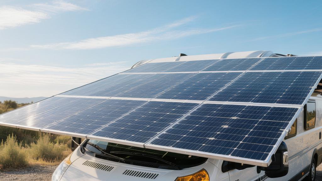
· Thin-film panels are seamlessly attached along the curved surface, maintaining the vehicle's original aerodynamic profile.
· The added frontal cross-sectional area from a mere 2 mm thickness is negligible in aerodynamic calculations.
· Laminar air can flow smoothly over the roof surface, remaining attached for longer and reducing drag caused by flow separation.
· The lack of a gap between the panel and the roof completely eliminates wind whistling noise generated when high-speed air passes through narrow spaces, improving acoustic comfort inside the cabin.
Temperature Differences
Standard test conditions are set at 25 degrees Celsius, but under direct summer sunlight, the actual working temperature of rooftop panels often exceeds 65 degrees Celsius.
The temperature coefficient for monocrystalline silicon is approximately a 0.4% power drop for every 1 degree Celsius increase.
In contrast, CIGS or Cadmium Telluride (CdTe) thin-film technologies have lower temperature coefficients, between -0.2% to -0.3% per degree Celsius.
In high-temperature environments, thin-film materials suffer less power loss.
Rigid panels rely on air convection in the 5 cm gap beneath them for heat dissipation; when the vehicle is stationary and there is no wind, convection efficiency is extremely low, causing heat to accumulate at the bottom.
Easy to Install
Weight Comparison
The weight of a traditional 100-watt rigid monocrystalline silicon solar panel is generally between 8 kg to 10 kg.
Moving a rigid panel onto a campervan roof 3 meters above the ground requires at least two adults working together, using ladders and lifting aids.
If accidentally dropped, the sharp aluminum alloy edges and tempered glass can cause physical scratches to personnel or the vehicle surface.
Thin-film solar panels use polymer substrates and CIGS or Cadmium Telluride materials; the weight of a module with the same 100-watt rated power drops to 1.5 kg to 2.2 kg.
A single person can carry a thin-film panel rolled into a cylinder with a diameter of about 15 cm to the installation site with one hand.
The roof structures of RVs or trailers are usually made of fiberglass composite materials 3 mm to 5 mm thick or aluminum plates 1 mm to 1.5 mm thick.
When laying rigid panels over a large area, it adds a static load of about 15 kg per square meter.
When a vehicle passes over speed bumps or unpaved roads at 100 km/h, the dynamic impact load brought by G-force is multiplied, forcing installers to weld additional aluminum internal skeletons for structural reinforcement.
The weight distribution of less than 3 kg per square meter is extremely uniform, and the original fiberglass or thin metal sheets of the roof will not undergo any measurable structural deformation under this weight.
Specifications (100W Power Standard) | Rigid Monocrystalline Panel | Flexible Thin-film Panel | Installer Requirement | Structural Reinforcement Requirement |
Physical Weight | 8 - 10 kg | 1.5 - 2.2 kg | 2 people | Internal skeleton required |
Transportation Form | Flat, non-foldable | Rollable (15 cm diameter) | 1 person | No structural changes needed |
Load per Square Meter | Approx. 15 kg | Approx. 2.5 kg | Requires mechanical hoist | Can be carried with one hand |
Adhesive Selection
A standard Z-bracket installation requires using a power drill to penetrate the roof with 4 to 8 mounting holes with diameters of 5 mm to 8 mm.
Installers must use electronic rangefinders and metal detectors to accurately locate the wooden joists or aluminum trusses inside the roof (usually spaced at 16 inches or 24 inches).
If #10 or #12 stainless steel self-tapping screws are only fixed to the thin top shell, wind resistance after a few hundred kilometers will tear the screws out by the roots.
Every penetration must be filled with Butyl tape and covered with self-leveling polyurethane sealant.
The back is typically pre-installed at the factory with acrylic foam double-sided tape (such as 3M VHB 4,950 series) or specified for use with marine-grade polyurethane structural adhesive (such as Sikaflex 252).
Installation labor is transformed into a simple surface chemical treatment process. The operator only needs to wipe the roof with a 70% or 90% Isopropyl Alcohol (IPA) solution to remove surface grease, dust, and oxidation layers.
After peeling off the release liner, applying a uniform pressure of about 100 kPa with a rubber roller completes the initial fixation.
At an ambient temperature of 21 degrees Celsius, VHB tape reaches 50% bonding strength within 20 minutes and 100% after 72 hours of curing, providing a tensile pull-off strength of up to 480 kPa.
Simplified Wiring
Traditional aluminum-framed solar panels are conductive; the National Electrical Code (NEC) has clear regulations for mobile power equipment requiring exposed metal frames to establish an independent Equipment Grounding Conductor (EGC).
Installing rigid panels requires drilling into the aluminum frame, using serrated grounding washers to penetrate the anodized layer, and connecting 6 AWG or 8 AWG bare copper wire to the vehicle chassis.
Thin-film panels use ETFE or PET polymers for full encapsulation, featuring no metal frame whatsoever, and are classified as Class II double-insulated equipment in terms of electrical safety.
The double-insulated design physically eliminates the risk of leakage to the vehicle's metal shell, completely removing the grounding wire installation step.
The junction box design of thin-film panels is extremely low-profile, with the height usually controlled between 8 mm and 10 mm, and the interior is filled with flame-retardant silicone for IP68-rated waterproofing.
The integrated 10 AWG or 12 AWG UV-resistant PV cables are typically very short, with MC4 connectors close to the panel edge.
Installers do not need to struggle with zip-tying excess cables in a 5 cm gap as they do with the large 25 mm thick junction boxes at the bottom of rigid panels.
Superior Performance
Weather Conditions
The standard for measuring the rated power of solar panels under Standard Test Conditions (STC) is an irradiance of 1000 watts per square meter.
In actual applications, mobile devices are often parked under tall trees, in the shadows of buildings, or encounter continuous rainy weather, where the actual received solar irradiance often plummets to levels of 200 to 400 watts per square meter.
The bandgap of monocrystalline and polycrystalline silicon solar cells is typically around 1.12 electron volts (eV), primarily absorbing red and near-infrared light waves in the visible spectrum between 500 nm and 900 nm.
The photoelectric conversion efficiency of crystalline silicon solar panels drops dramatically in low-light environments dominated by blue light or diffuse reflection.
The bandgap of thin-film materials like CIGS or Cadmium Telluride (CdTe) can be adjusted between 1.0 eV and 1.7 eV based on elemental ratios, with a spectral response range covering everything from short-wave blue light at 400 nm to long-wave infrared at 1200 nm.
When a campervan is parked in a rainy forest park in Washington state, the output current of a 100W monocrystalline panel on the roof may drop below 0.5 Amps, barely meeting the charging threshold of an MPPT controller.
A nearby 100W thin-film solar panel of the same rated power can still maintain a stable current output of 1.5 Amps to 2.5 Amps, continuously trickling a charge into the 12V deep-cycle lead-acid or lithium iron phosphate batteries inside the cabin.
In all-weather operation tests lasting 12 months, thin-film solar modules worked an average of 1.5 to 2 hours longer per day than crystalline silicon modules under low-light conditions, increasing the overall annual power generation.
Shade Tolerance
Traditional crystalline silicon solar panels are composed of 36 or 72 independent silicon wafers connected in series by small metal busbars.
When a leaf with an area of only 15 square centimeters completely shades one silicon wafer, that wafer instantly shifts from a power generation unit to a power-consuming load, creating a localized "hot spot" effect.
To prevent hot spots from burning out the panel, manufacturers install 2 to 3 bypass diodes in parallel inside the junction box on the back of crystalline panels.
Once a single cell is shaded, the current is forced to bypass the entire series unit containing that cell, causing the overall output power to drop instantly by 33% or even 50%.
Thin-film cell layers are divided into long strips using laser-scribing technology during manufacturing and are internally connected in a high-density parallel or series-parallel matrix structure.
If shade covers 10% of the physical area of a thin-film panel, the overall power generation will only see a linear decrease of about 10%.
Partial shading is the primary physical reason for sharp declines in the efficiency of mobile photovoltaic systems. The high-density parallel circuit structure of thin-film materials can still provide over 40% of rated power output when subjected to irregular tree shade covering 50% of the area.
Total Energy Yield
The actual energy produced by a 400W photovoltaic system in one day is usually measured in watt-hours (Wh) or kilowatt-hours (kWh).
Due to the Earth's rotation and the constant changes in the orientation of mobile devices, solar panels installed on horizontal roofs are unable to maintain a perfect 90-degree perpendicular incident angle with sunlight for most of the day.
The ETFE polymer coating on thin-film solar panel surfaces is typically embossed with a fine concave-convex texture (such as a honeycomb or frosted texture).
This microstructure can subject tilted light from large incident angles (such as dawn or dusk at a 15-degree to 30-degree angle to the horizon) to multiple refractions, capturing and funneling it into the photoelectric conversion layer below, significantly reducing optical reflection losses.
In a controlled 30-day experiment in the arid climate of the American Southwest, two identical trailers were horizontally fitted with 600W crystalline silicon solar arrays and 600W CIGS thin-film solar arrays respectively.
Recorded data showed that while the instantaneous peak power of the crystalline silicon array was indeed higher during midday, the CIGS thin-film array—thanks to its wider spectral absorption band, superior shade resistance, and longer daily operating hours—delivered over 72 kWh of total energy to the cell banks over the 30-day period.
In comparison, the cumulative power generation of the crystalline array was only 61 kWh.
The extra 18% of generated power allowed the campervan equipped with thin-film panels to run an additional 12V compressor refrigerator for an entire week without being connected to shore power.
The ultimate metric for evaluating mobile photovoltaic systems is all-weather cumulative power generation, not peak power at a single moment. The high availability of thin-film technology under non-ideal sunlight conditions changes the energy balance equation for off-grid environments.