How to Reduce Rear-Side Loss in Bifacial Modules | Rails, Junction Boxes, Row Spacing
Bifacial modules increase energy yield by using both front-side irradiance and rear-side reflected light. The actual rear-side gain depends on albedo, module height, tilt, row spacing, tracker geometry, soiling, snow cover, and rear-side obstruction. Because these variables interact, rear-side gain should be treated as a site-level result rather than a fixed module-datasheet number[1].
Rear-side loss usually comes from six causes: blocked rear irradiance, weak ground reflection, uneven illumination, local heat build-up, electrical mismatch, and row-to-row shading. This article focuses on three installation variables that most often decide whether a bifacial project performs close to its design model: mounting rails, junction boxes, and row spacing.
Installation Variable | Main Rear-Side Risk | Field Check Priority |
Mounting rails | Rear irradiance blockage, continuous shadow bands, deflection, grounding issues, and clamp fatigue | Rail width, rail direction, module clearance, span, support, and fastener torque |
Junction boxes and cables | Local shading, diode heat, cable-loop shading, sealing failure, and insulation ageing | Box position, thermal path, box gap, cable bend radius, cable restraint, and connector sealing |
Row spacing | Front-to-rear shading, uneven ground illumination, alignment error, and land-use trade-off | Winter-solstice shadow, albedo, slope, vegetation, service aisle, and cleaning access |
IEC 61215, IEC 61730, and IEC TS 60904-1-2 are useful references for module qualification, safety, and bifacial measurement. They should not be used as direct formulas for rail layout, junction-box placement, or row spacing. Final design still requires project-specific optical, structural, electrical, and O&M modelling[2].
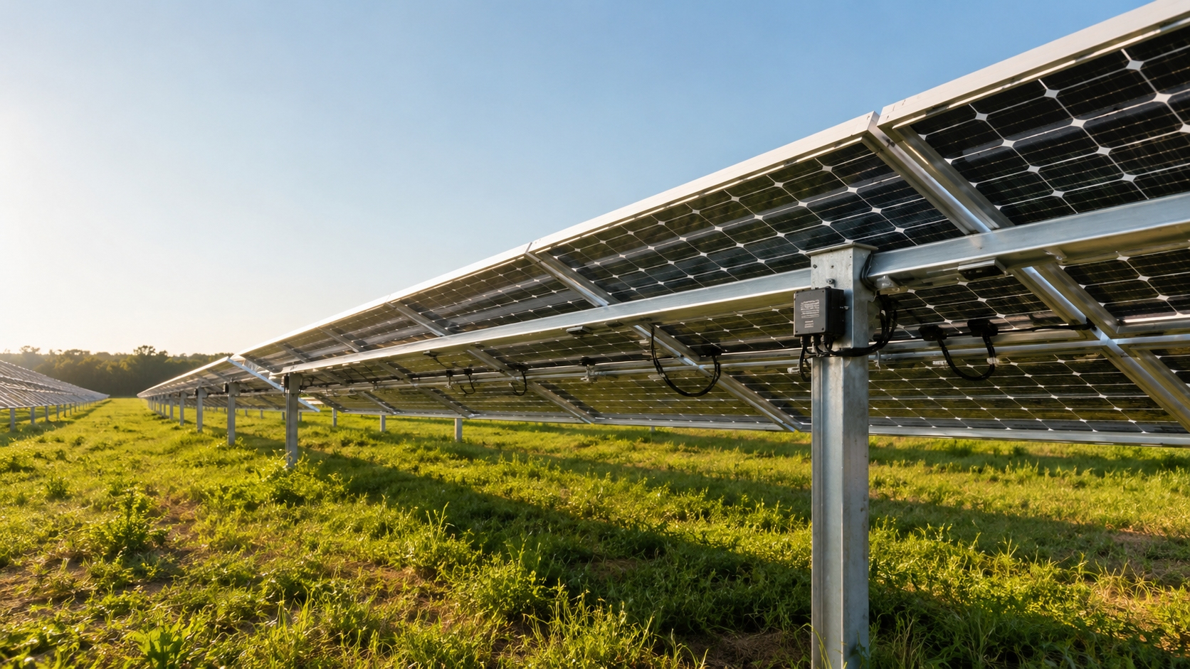
Mounting Rails
Rail Shading Area
Cross rails can shade rear cells directly. Increasing rail width from 35 mm to 50 mm expands the projected rail width by about 43%, so the rear-side optical penalty can rise quickly when the rail crosses active cell areas.
In one field comparison under similar tilt, row spacing, and ground-cover conditions, a 35 mm aluminium cross beam caused about 1.6% rear irradiance shading, while a 50 mm steel beam caused about 2.8%. These values should be treated as project-specific measurements, not universal design constants.
Rail Scheme | Observed Rear Irradiance Shading | Practical Meaning |
35 mm aluminium cross beam | About 1.6% | Lower direct rear-side obstruction |
50 mm steel beam | About 2.8% | Higher risk of optical loss and local mismatch |
Rail shading should not be judged by width alone. The same rail can produce different loss when module height, ground albedo, module tilt, and rail direction change.
l Keep rails away from the rear active cell area where the approved module design allows it.
l Avoid continuous shadow bands across the same rear-side cell string.
l Follow the manufacturer's approved clamp zone and structural load requirements before reducing rail size.
l Use calibrated torque tools; the torque value should follow the clamp, rail, and bolt supplier's specification.
l Check grounding continuity after installation and again after the first settlement or vibration cycle.
Material choice also matters. Aluminium rails often reduce obstruction and corrosion-staining risk compared with bulky or poorly protected steel members, but the final selection must still satisfy wind load, snow load, span, galvanic corrosion control, and local structural code.
When the span is long, reducing rail width without adding support can create more risk than it removes. Mid-span deflection can open a gap between the rail clip and the module frame, increasing vibration fatigue, water ingress, and local thermal resistance.
Rail Height Selection
Rail height affects rear-side view factor, snow clearance, maintenance access, and rear irradiance distribution. Raising the module often helps the rear side see more reflected ground light, especially on high-albedo surfaces. However, height should be optimized together with row spacing, tilt, wind load, tracker range, foundation design, and ground treatment.
For snow-prone sites, minimum clearance should be checked against maximum snow depth, drifting risk, service-road layout, and cleaning method. A simple clearance rule such as H ≥ R + 0.5 m, where R is maximum snow depth, may be useful as a first-pass check, but it cannot replace winter shading and O&M modelling.
l Below about 0.5 m, snow burial and maintenance access usually become more difficult.
l A clearance around 0.6-1.2 m is common for many fixed-tilt ground projects, but the final value should be site-specific.
l Aquavoltaic and coastal projects may need higher clearance for water operation, corrosion control, and inspection access.
l Higher clearance can increase structural demand and wind exposure, so it must be checked with foundation and frame-fatigue design.
For coastal or salt-spray environments, PV modules should be selected for the appropriate salt-mist corrosion condition. IEC 61701 is the relevant PV module salt-mist corrosion testing standard; the site design still needs corrosion-resistant fasteners, drainage paths, cable sealing, and regular insulation checks[3].
Rear-Side Light Path
Rail direction affects whether shading appears as small isolated patches or as a continuous shadow band. A continuous band is more dangerous because it can align with active cell strings and create current mismatch across a whole substring.
For fixed-tilt arrays, support members should be arranged to reduce long rear-side shadow bands. For single-axis trackers, rails, torque-tube attachments, and cable paths should be checked through the full tracker rotation range because morning and afternoon shadows may be more severe than noon shadows.
l Inspect rear irradiance in the morning, at noon, and in the late afternoon.
l Check whether rail shadows cross active rear cells or mostly fall in inactive gaps.
l Compare rear-side irradiance between rows that should have identical geometry.
l Use string current and infrared thermography together; a small optical shadow can create a larger electrical mismatch.
Ground reflectance is part of the same rear-side light path. Albedo should be measured or modelled for the real site surface rather than copied from a generic table, because soil moisture, snow, crop growth, dust, and ground-cover ageing can change reflected irradiance throughout the year. NREL's solar resource guidance also emphasizes the importance of using appropriate irradiance data and measurement practice for solar energy modelling[4].
Ground Surface | Typical Engineering Range | Design Note |
Grass or mixed soil | About 0.15-0.25 | Seasonal vegetation and moisture can change rear gain. |
Concrete or light gravel | About 0.25-0.40 | More stable than vegetation, but dust and ageing still matter. |
White ground cover or coating | About 0.50-0.70 when clean | High initial albedo, but cleaning and ageing must be included. |
Snow cover | Often high but unstable | Can improve winter reflection but also creates burial and drift risk. |
Junction Boxes
Junction-Box Shading Footprint
A standard junction box can look large from the rear, but its real shading impact depends on whether it sits over an inactive gap or over active rear cells. A slightly larger box placed in a low-sensitivity rear area can be better than a smaller box that runs hotter or forces poor cable routing.
Junction-Box Detail | Rear-Side Effect | Design Meaning |
Standard box around 110x90x25 mm | Low direct area loss when placed over an inter-cell gap | Acceptable if thermal path and sealing are stable |
Higher box with cooling fins | Slightly larger rear projection | May be justified if diode temperature is lower |
Miniature box | Lower projected shading | Risky if it increases diode temperature or cable stress |
The design target is not simply to minimize box size. The box should stay outside the most active rear-light path, keep the diode thermal path short, maintain adhesive-line consistency, and avoid cable loops across the rear active area.
l Check whether the box sits over an inactive rear zone.
l Check whether the adhesive bond line is uniform.
l Check whether cable loops hang below the box and shade active cells.
l Check whether the box runs hotter than neighbouring rear surfaces under similar irradiance.
Cable Routing Plan
Cable shading is small per module but can become measurable across thousands of modules. Repeated cable loops, sagging connectors, and poorly tied bundles can create cumulative rear-side loss at plant level.
Cables should be held close to the frame or approved support path, but not so tightly that thermal expansion, wind vibration, or tracker movement damages insulation. For tracker systems, the cable path must remain clear through the full tracker rotation envelope.
Project Type | Cable-Routing Priority |
Fixed-tilt ground plant | Keep cable drops close to the frame and away from active rear cells. |
Single-axis tracker | Protect dynamic bend radius, torsion allowance, and rotation clearance. |
Rooftop project | Avoid sharp edges, water ponding, connector contact with roof surfaces, and unsupported cable loops. |
Aquavoltaic or high-humidity site | Prioritize connector sealing, UV resistance, insulation monitoring, and corrosion control. |
l Use UV-rated outdoor PV cable and approved cable ties or clips.
l Keep cable bend radius within the cable manufacturer's specification.
l Avoid over-tight ties that restrict cable movement.
l Keep connectors away from wet surfaces and standing water.
l For rodent-prone sites, use cable trays, guards, or armoured routing where justified.
l Size grounding conductors according to local electrical code, fault-current calculation, and equipment requirements.
PV O&M guidance from NREL emphasizes that inspection should combine visual checks, infrared thermography, electrical measurements, and maintenance records rather than relying on one diagnostic method alone[5].
Rear-Side Heat Build-Up
Rear-side shading near the junction box can become a thermal and electrical issue. When heat cannot convect away, the diode and nearby encapsulation run hotter, leakage current increases, and bypass behaviour can shift under partial shading.
In one aquavoltaic field comparison, arrays with a box-to-backsheet gap near 10 mm ran about 18-22℃ hotter inside the box than arrays with a gap near 20 mm under comparable water-surface conditions. This should be treated as a site-specific warning, not a universal specification.
l Use the module maker's rated junction-box temperature and diode specification as the design boundary.
l Check adhesive thickness and uniformity because it affects the thermal path.
l Use infrared thermography together with string-current data.
l For humid or water-surface projects, inspect sealing, potting ageing, breather valves, and insulation resistance more often.
l If string current fluctuates without a clear inverter cause, use temporary higher-frequency logging around suspected strings before replacing modules.
For floating, aquavoltaic, or humid installations, damp heat, sealing, and corrosion risk should be treated as system-level issues. IEC 61215 and IEC 61730 qualification help screen module design, but field reliability still depends on installation workmanship, connector protection, humidity exposure, and maintenance discipline[6].
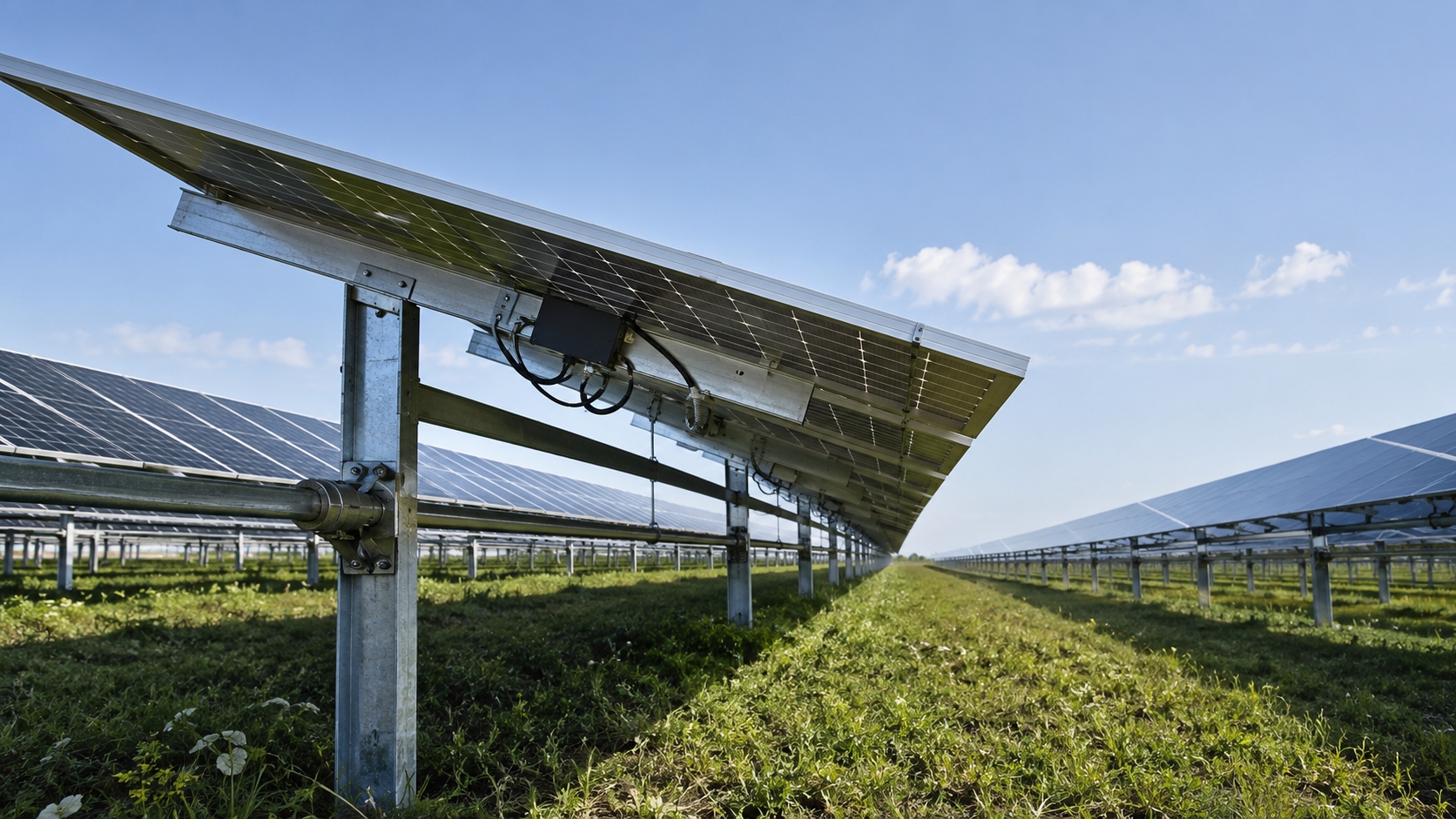
Row Spacing
Ground Illumination
Row spacing controls how the front row casts shadows onto the ground and onto the rear side of the next row. The critical check should be made at low winter solar altitude, not only at annual average conditions.
For Beijing, winter-solstice noon solar altitude is about 27°, not 30°. This matters because low winter sun stretches the front-row shadow and can darken the rear lower cell area if row spacing is too tight[7].
A useful first-pass spacing relationship is D = H x cot(alpha) + margin, where D is row spacing, H is the relevant height difference, and alpha is the design solar altitude. The margin should cover module tilt, terrain slope, installation tolerance, vegetation, snow drift, service aisle, and cleaning equipment.
Ground Condition | Rear-Side Effect | Spacing Implication |
Low-albedo grass or soil | Less reflected rear irradiance | Wider spacing alone may not recover rear gain. |
Light concrete, gravel, or coating | Higher reflected rear irradiance | Spacing and ground treatment should be optimized together. |
Agri-PV with seasonal crops | Crop height changes shadow geometry | Add clearance for crop growth and maintenance access. |
Snow-prone ground | High reflection but high burial or drift risk | Check both winter gain and snow-management cost. |
Albedo gain is often most visible in the morning and late afternoon, when direct beam intensity is lower and diffuse or reflected light has a larger relative contribution. A noon-only inspection can miss rear-side underperformance during these operating windows.
A complete ground-illumination check should include:
l row spacing;
l front-edge and rear-edge height;
l module tilt and azimuth;
l terrain slope and slope direction;
l ground cover and albedo ageing;
l seasonal vegetation height;
l snow, mud, dust, or water persistence;
l cleaning vehicle and inspection access.
Rear-Side Shading Control
Front-to-rear shading is the obvious risk of tight spacing, but intra-array shading is often overlooked. A small short-edge offset between adjacent modules can turn into a long rear-side shadow strip when repeated across a row.
In one field comparison, offset-mounted arrays underperformed better-aligned arrays by about 1.8%. The practical fix is to align top and bottom short edges with a laser line or equivalent tool and to re-check alignment after foundation settlement.
l Use installation tolerances that prevent repeated rear-side shadow strips.
l Check short-edge alignment after module mounting and cable binding.
l Re-check rows after cleaning-equipment commissioning.
l On soft soil, inspect settlement after the first rainy season or freeze-thaw cycle.
l Separate human inspection aisles from cleaning-equipment aisles.
Access Type | Typical Design Need | Reason |
Manual inspection | At least about 0.6 m where local safety rules allow | Basic access without routine equipment passage |
Small cleaning equipment | Often about 1.2 m or more | Cleaner width, turning space, and cable safety |
Large automated cleaning equipment | Often about 1.8 m or more | Equipment clearance, wheel path, and collision prevention |
Row Spacing vs Generation Trade-Off
More row spacing is not automatically better. Wider spacing may improve rear uniformity and reduce winter shading, but it also reduces installed capacity per unit land and can raise cable, foundation, and O&M cost.
The correct optimization target is project value per unit land, not rear-side gain alone. In agrivoltaic or dual-use land projects, land equivalent ratio is often used to compare combined outputs from the same land area[8].
Latitude Case | Spacing Change | Generation Change | Land Change | Net Per-Land Result |
40° N | 2.0 m to 3.0 m | +5.7% | +9% land | About 3.0% drop per unit land |
22° N | 2.0 m to 3.0 m | +7.4% | +9% land | About 1.5% drop per unit land |
These examples show why spacing can improve total generation while still reducing generation per unit land. The result depends on latitude, winter solar altitude, albedo, land cost, structural cost, cleaning access, and the value of the extra energy.
l Cheap desert land may justify wider spacing if extra energy and lower maintenance risk outweigh land cost.
l Rooftop or land-constrained projects may prefer higher power density even with lower rear uniformity.
l Agri-PV layouts must also protect crop yield, machinery access, and seasonal crop height.
l Wind-exposed sites may gain structural benefit from wider spacing because inter-row wind interaction can change frame loading.