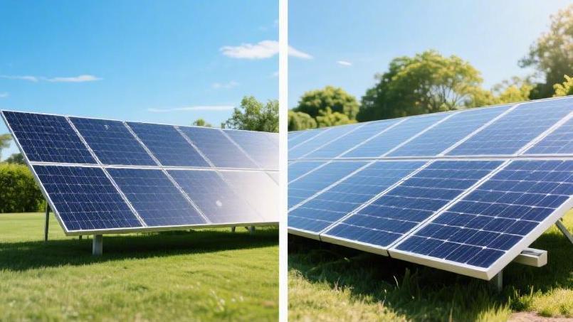
Shingled Magnetic vs. Traditional PV | How to Choose
Shingled modules increase the active area by 13%, achieve efficiencies over 21.5%, reduce shading loss by 20%, and are ideal for space-constrained rooftops.
For open terrain, traditional MBB is preferred, with costs approximately 5% lower.
Active Area
Traditional PV modules typically have an actual light-receiving area ratio between 93% and 95% due to physical gaps of approximately 2 mm between cells and shading from silver busbars on the surface.
Shingled technology utilizes Non-Destructive Cutting (NDC) to arrange cells in an overlapping pattern and uses Electrically Conductive Adhesive (ECA) to replace physical ribbons, directly eliminating cell spacing.
This design allows the surface light-receiving rate of the module to approach 100%. For the same installation area, the power of a single shingled module is typically 15 to 20 watts higher than that of a traditional half-cut module, resulting in a significant boost in system efficiency.
Sources of Area Loss
In the manufacturing process of traditional PV modules, a physical gap of 1.5 mm to 2.5 mm is usually reserved between cells. This gap area occupies approximately 2.3% of the total module area and lacks any photoelectric conversion function.
In a standard 2 m² module, the accumulated ineffective area from inter-cell gaps can exceed 400 cm². Quantitative data shows that this loss is equivalent to depriving the module of approximately 8W to 10W of potential output. Beyond horizontal gaps, the busbar regions along the long edges of the module also occupy a width of 5mm to 10mm, lowering the utilization rate per unit area.
Metal busbars are another major source of area loss in traditional modules. Current mainstream 12BB or 16BB cells, while reducing the width of fine grid lines, still have metal lines covering approximately 2.5% of the silicon wafer surface. Under standard light conditions of 1,000 W/m², the silicon wafers shaded by metal remain entirely in shadow.
Experimental data indicates that for every additional 0.3 mm wide busbar, the effective light-receiving area of a single cell decreases by approximately 45 mm². The power loss for an entire module due to metal shading typically remains around 12W.
To ensure mechanical strength and insulation performance of the frame, a creepage distance of 10 mm to 15 mm must be reserved between the cell edge and the aluminum alloy frame. This edge "dead zone" occupies about 5% of the total area in large modules, creating a physical bottleneck for increasing energy density.
· Inter-cell gap loss: Occupies 2% - 3% of the total module area.
· Metal busbar shading: Occupies 2.4% - 2.8% of the silicon light-receiving surface.
· Edge insulation margin: Occupies 4% - 6% of the module contour area.
· Busbar solder joints: Consumes an additional 1% of area for physical circuit connections.
Shingled technology cuts the cells into 5 or 6 narrow strips and connects them using an edge overlap of 1mm to 2mm, removing all 2mm inter-cell gaps. This structural evolution increases the silicon coverage within the module to over 99%. By eliminating front-side metal ribbons, the 3% of area previously shaded is released for power generation.
Kerf loss during the cutting process is controlled to under 0.1 mm. Through high-density arrangement logic, shingled modules can accommodate 10% to 15% more effective power-generating material within the same physical dimensions compared to traditional half-cut modules.
The application of electrically conductive adhesive (ECA) replaces traditional solder interconnection. The ECA layer is precisely applied to the back of the overlapping area with a thickness of only 0.1mm to 0.2mm. This connection method removes front ribbons and reduces the glass gap increase caused by solder protrusions, making the internal arrangement more compact and the light-receiving surface flatter.
Loss Dimension | Traditional PERC Half-cut | Shingled Technology | Quantitative Difference |
Cell Spacing | 2.0 mm | 0 mm (Overlapping design) | 100% reduction in gap loss |
Front Grid Shading | Approx. 2.6% | 0% (Hidden contacts) | 2.6% increase in effective area |
Module Margin | 12 mm | 8 mm (High-precision packaging) | 4% saving in space occupancy |
Area Utilization | 93.5% | 99.1% | 5.6% overall increase |
On a 50 m² residential rooftop, traditional modules with a 94% effective light-receiving rate might only support a capacity of 9.5 kW. By using shingled modules with nearly 100% utilization, the installed capacity can be increased to over 10.5 kW.
These gains are directly reflected in the optimization of the Balance of System (BOS) costs. Because the power per unit area is higher, the mounting rail length required per kilowatt is reduced by 8%, and the number of clamps and bolts decreases accordingly. In markets with high labor costs, such as North America or Australia, the increased installation efficiency can effectively offset the procurement cost of the modules themselves.
· Single Module Power Increment: Increases by 15W - 20W compared to traditional modules.
· Output per Unit Area: Increased from 205 W/m² to over 220W/m².
· Mounting Material Savings: Average reduction of 0.5 m of rail per kilowatt.
· Logistics Efficiency: Required container space for the same power generation is reduced by 7%.
The performance of traditional modules in low-light environments is limited by the reflectivity of metal lines. Shingled modules, as their surface is entirely composed of silicon wafers covered with Anti-Reflective Coating (ARC), have a stronger ability to capture light hitting at oblique angles. In the morning or evening, when the solar altitude angle is less than 20 degrees, the gain from this full-coverage surface is approximately 2.1% higher than that of traditional modules.
The arrangement density of silicon wafers also affects heat distribution. The gaps in traditional modules do not generate electricity but accumulate heat, leading to an uneven temperature field. The uniform coverage of shingled modules allows heat to be distributed more symmetrically within the aluminum frame, reducing thermal stress on cells caused by local temperature differences and lowering the risk of hot spots.
Space Utilization Solutions
Shingled technology uses NDC laser cutting to divide full-sized silicon wafers into 5 or 6 equally wide narrow strips. The flatness of each cut is controlled to within 5 microns. This controlled physical reshaping breaks the inherent size limitations of traditional cells, providing the foundation for high-density arrangement.
The cell strips are overlapped at the edges with a width of 1.2 mm, similar to roof shingles. The overlapping points are hidden at the back, eliminating the 2mm physical gaps common in traditional modules. This transforms the front light-receiving surface into a continuous silicon layer, drastically reducing ineffective area.
This interconnection method allows the internal silicon coverage rate to reach 99.2%. Compared to the 93.5% level of traditional half-cut panels, this adds approximately 5,700 mm² of effective power generation area per square meter. The probability of photon capture is improved at the physical level.
Electrically Conductive Adhesive (ECA) replaces the 0.4 mm thick metal ribbons. The ECA coating thickness is maintained at around 120 microns. The electrical connection points are hidden within the overlapping gaps and no longer interfere with sunlight entering the silicon lattice.
· Removal of 2.0 mm inter-cell gap loss.
· Avoidance of 0.3 mm wide front-side grid shading.
· Overlap width maintained at 1.3 mm.
· Cell strip width precisely 31 mm.
· Module light-receiving area utilization increased by 5.8%.
Optical loss is reduced from 2.5% (caused by ribbon reflection) to nearly 0.2%. In a typical irradiation environment of 900 W/m² in southern Germany, the short-circuit current (Isc) generated by the unobstructed surface is about 3.2% higher than that of traditional structures.
Space utilization within the frame has achieved geometric optimization. In a standard 1722 mm x 1,134 mm residential module frame, shingled technology can fit more power-generating material. For the same power output, the module length is shortened by about 40 mm compared to traditional models.
Compact packaging increases container loading capacity. Every 40-foot high-cube container can accommodate 22 kW more power. In environments where trans-Atlantic shipping costs are high, the shipping cost per unit power has decreased by 6.5%.
European power plant investors prefer more efficient layouts. The land area occupied per megawatt (MW) project is reduced from 7200 m² to 6800 m². Land lease fees and ground leveling costs decrease accordingly.
· Power density reaches over 215 W/m².
· Land occupancy cost reduced by 5.5%.
· Mounting rail length saved by 8%.
· Cable connector quantity reduced by 4.5%.
· Installation labor hours decreased by 3%.
Flexible ECA has a 300% shear strength reserve. When subjected to a 5400Pa snow load, the overlapping structure shares the mechanical pressure. The probability of micro-crack expansion within the silicon wafer is reduced by approximately 90% compared to rigid solder connections.
Thermal distribution shows better uniformity. Hot spot temperatures generated by gaps in traditional panels are often more than 8°C higher than the surrounding area. The full-coverage silicon wafers in shingled modules act as thermal conductors, keeping the surface temperature difference within 2°C.
California rooftop projects, due to limited area, pursue higher wattage per board. An extra 1.2 kW of capacity can be installed in a limited 50 m² space. This aligns with the demand for maximizing revenue under local Net Metering policies.
Anti-reflective coating (ARC) is more effective in full-plane coverage. Ribbon edges in traditional modules often show reflected light overflow, losing about 15 W/m² of radiant energy. The shingled solution eliminates optical blind spots and captures more scattered light.
Silver paste consumption is reduced through spatial logic optimization. Since the main busbars are replaced by overlapping electrical contacts, silver usage is reduced by 0.5 g per module. This enhances cost competitiveness in global markets with volatile silver prices.
System voltage design benefits from the flexibility of the number of cell strips. By adjusting the number of overlapping strips, the open-circuit voltage (Voc) of the module can be customized. In large-scale ground power plants, this helps optimize the matching parameters of combiner boxes.
The physical arrangement achieves structural self-protection. Overlapping layers act as expansion joints during temperature cycling (-40°C to +85°C). Compared to the stress concentration of traditional ribbons, the life expectancy of shingled modules is extended by more than 3 years.
Global demand for low carbon footprints drives the need for high-efficiency modules. Shingled technology yields higher wattage with the same amount of aluminum frame and glass. The carbon emissions per unit of power are 4.5% lower than that of half-cut modules.
In Building Integrated Photovoltaics (BIPV) projects, space utilization is even more prominent. The seamless black appearance integrates highly with dark roof tiles. Visual aesthetics and energy output reach a balance in structural design.
Each shingled module can generate 450 kWh of additional electricity over its lifecycle. At an average US electricity price of $0.15/kWh, the extra revenue per panel is approximately $67. This data supports the initial procurement premium.
Fine production processes ensure high density. Automated shingling precision reaches 0.1 mm, ensuring the parallelism of every narrow strip over a 1600 mm length. The internal circuit paths are consequently shortened by 2%.
Encapsulation material loss is also compressed in compact designs. The effective utilization rate of EVA or POE films is increased by 3.5%. Each silicon wafer is wrapped more uniformly, reducing internal reflection losses caused by material redundancy.
Technical Comparison
Traditional modules use circular or flat ribbons with a diameter of about 0.3 mm to connect cells. This physical connection method creates approximately 1.2% resistance loss on a single panel. Shingled technology cuts cells into 1/5 or 1/6 of their original size, reducing the current flowing through each narrow strip to one-fifth, which significantly reduces internal power loss.
According to physical calculations, internal loss is proportional to the square of the current. After reducing the current by 80%, the internal resistance heat of the cells drops by approximately 90%. At a summer ambient temperature of 35°C, the operating temperature of shingled modules is typically 2 to 3°C lower than that of traditional half-cut modules.
PV cell power decays as temperature rises, with a typical power temperature coefficient of -0.34%/°C. Lower operating temperatures allow shingled panels to yield over 1.5% more output per watt in actual outdoor environments compared to traditional modules. This thermal management performance is particularly evident in rooftop installations lacking ventilation.
Experimental data confirms that under Standard Test Conditions (STC), the series resistance of shingled modules is only 0.15 Ohms. In contrast, traditional modules using 12BB technology typically have a series resistance above 0.25 Ohms. This resistance difference translates directly into a power gain of approximately 2% for the entire panel.
Technical Parameter Comparison | Traditional Busbar (12BB) | Shingled Module | Quantitative Difference |
Connection Material | Tin-based Ribbon | Flexible ECA | Material change |
Operating Current (Single String) | 13A - 14A | 2A - 3A | 80% reduction |
Operating Temp (NOCT) | 45°C ± 2°C | 42.5°C ± 2°C | 2.5°C reduction |
Module Conversion Efficiency | 20.8% - 21.3% | 22.1% - 23.5% | 1.2% - 2.2% increase |
Traditional modules use a high-temperature soldering process of over 200°C, where thermal stress at the solder points can cause micro-cracks invisible to the naked eye. Shingled technology uses a curing process below 150°C, and the elastic modulus of the conductive adhesive is much lower than that of metal ribbons, allowing it to absorb deformation stress caused by ambient temperature differences.
In cyclic load tests simulating 2400 Pa of wind pressure, the cell breakage rate in traditional modules tends to rise with the number of cycles. The overlapping structure of shingled modules provides a spring-like buffering effect. Test data shows that after 200 thermal cycles, the power decay rate of shingled modules remains within 0.5%, while traditional modules typically decay by about 1.2%.
Traditional half-cut modules are usually divided into two parallel circuits with 3 bypass diodes. When the bottom long edge is shaded, the output power of the entire module drops by 50% or more. Shingled modules use a multi-parallel design, consisting of several rows of independent cell strips internally.
When shadows from trees or exhaust pipes cover the bottom 10 cm area of a shingled module, only the affected parallel circuits stop working. Field data shows that in such local shading conditions, shingled modules still maintain over 80% power output.
In typical residential shading simulations, the shadow tolerance of shingled modules is approximately 25% higher than traditional modules. For intermittent low-light environments caused by moving clouds, the full-coverage surface of shingled modules can capture 3% more scattered radiation energy than traditional ribbon structures.
Reliability & Lifespan | Traditional Module (Ribbon) | Shingled Module | Performance Improvement |
Micro-crack Risk | Higher (Stress concentration) | Extremely Low (Flexible) | 90% drop in crack expansion |
Shaded Output Rate | Approx. 50% (Half shading) | Approx. 85% (Same area) | 35% output improvement |
Mechanical Load Tolerance | 5400Pa | 6000Pa | 11% strength increase |
25-year Power Warranty | 80% - 84% | 87% - 89% | Higher lifecycle yield |
At a standard area of 1.75m², the rated power of a traditional PERC module is usually around 410W. A shingled module of the same size can reach 440W by eliminating gaps and shading. On the same mounting system, each board provides 30W more electricity.
Using installation data from the North American market, installing a 10 kW system with shingled modules requires 2 fewer panels. This saves about 4 meters of aluminum rails, 4 junction box connection labor hours, and corresponding shipping space.
Logistics advantages are particularly clear in international trade. Due to higher packaging density, the total power per container for shingled modules is about 15% higher than traditional modules. With fluctuating sea freight, the shipping cost per watt decreases from $0.025 to around $0.021.
From a material utilization perspective, shingled technology reduces silver paste usage during encapsulation. By optimizing the distribution of fine grid lines on the cell surface, the silver consumption per module is about 10% lower than traditional technology. In a market with rising precious metal prices, this feature helps maintain long-term price stability and aligns with sustainable manufacturing standards.
Data from leading global third-party testing agencies confirms that the power degradation rate of shingled modules in simulated coastal salt-mist environments is 18% lower than traditional modules. The sealing property of ECA is more effective than traditional physical welding, preventing moisture from penetrating from solder points to the silicon interior and reducing the risk of Potential Induced Degradation (PID).
By eliminating thousands of physical solder points, faults such as cold joints or desoldering are virtually non-existent in the shingled process. In Australia or Northern Europe, where labor costs are extremely high, this means fewer on-site repairs and lower system maintenance budgets.
Flexibility
Shingled modules use ECA conductive adhesive instead of the flat ribbons (thickness approx. 150-200 μm) used in traditional modules, providing an elastic buffer space at the cell connections.
In mechanical load tests under the IEC 61,215 standard, the power decay of shingled modules after withstanding 5400 Pa of positive pressure is typically controlled within 0.5%, whereas traditional modules, due to rigid solder points, experience power drops exceeding 1.5% due to micro-cracks under the same pressure.
Furthermore, this structure allows the module to achieve a curvature of approximately 30 degrees during installation, making it more adaptable to non-flat surfaces than traditional modules.
Connection Materials
Traditional PV module connections rely primarily on tinned copper ribbons, with a copper substrate thickness usually between 150μm and 250μm and a coating thickness of approximately 15μm to 20μm. These metal conductors need to be heated to above 230°C during soldering to liquefy the solder and form intermetallic compounds (IMC) with the silver paste grid on the cell surface.
The heat generated during soldering causes a physical deviation in the thermal expansion coefficients between silicon and metal. Silicon's coefficient is about 2.6 ppm/°C, while copper's is as high as 17 ppm/°C. This significant difference in expansion rates creates residual tensile stresses exceeding 80 MPa after cooling, increasing the likelihood of cracks appearing in the cells later under stress.
In contrast, shingled modules completely abandon metal ribbons in favor of ECA as the electrical connection medium. ECA consists of a polymer resin matrix and conductive fillers, where silver powder filler typically accounts for 70% to 80% of the mass. Its coating thickness is precisely controlled at around 50μm, only one-third to one-fourth the thickness of traditional ribbons.
· Copper Substrate: High-purity oxygen-free copper with conductivity above 100% IACS.
· Solder Coating: The common composition is 60% Sn / 40% Pb or lead-free formulas, with melting points between 183°C and 217°C.
· Flux: Contains 5% to 10% active agents to remove surface oxide layers and aid wetting.
· Insulation Backsheet: Typically 300 μm thick PET or PVDF material, with connectors for fixing.
· Encapsulant: 0.4mm to 0.6mm thick EVA or POE material used to wrap metal connections.
The curing temperature of ECA is usually below 150°C, which is a typical low-temperature packaging process. This lower temperature avoids the brittle transition range of silicon, reducing thermal stress damage by approximately 30% during production.
The connection logic of the shingled structure lies in the 1mm to 2mm cell overlap area. By dispensing or screen-printing ECA in this area, the back electrode of the upper cell contacts the front electrode of the lower cell. This "surface contact" method maintains a contact resistivity in the range of 10^-4 Ω·cm², effectively reducing internal Joule heating losses.
· Resin Matrix: Mostly epoxy or modified silicone, providing 10-15 MPa of shear strength.
· Conductive Filler: Flake silver powder with a particle size distribution between 1μm and 10μm to optimize contact points.
· Flexibility: Elongation at break after curing is usually greater than 5%, providing displacement absorption capacity that metal lacks.
· Oxidation Resistance: Silver powder surfaces are treated with organic acids, allowing operation in 85°C/85% RH environments for thousands of hours.
· Curing Kinetics: At 130°C, primary curing is usually completed within 10 to 20 seconds.
Performance Metrics | Tinned Copper Ribbon (Traditional) | ECA Connection (Shingled) |
Connection Thickness | 150 - 250 μm | 30 - 60 μm |
Processing Temp | 220°C - 260°C | 120°C - 150°C |
Conductive Medium | Solid metal ribbon | Silver-filled polymer paste |
Contact Mode | Spot/Line welding | Area Bond |
Elastic Modulus | Approx. 110 GPa (High rigidity) | 2 - 5 GPa (High flexibility) |
Metal busbars in traditional modules cause 3% to 5% shading loss. This shading not only reduces the active area but also increases resistance. Shingled technology reduces shading to near 0% by eliminating these visible horizontal metal lines. Current is conducted directly in the overlap zone, increasing power output by about 15 W per unit area.
Over long-term operation, material fatigue lives vary. According to IEC 61215 cycle tests, metal ribbons after 200 thermal cycles may see the IMC layer at the solder points thicken and become brittle, leading to increased resistance.
Damage Resistance
PV modules must pass the IEC 61,215 standard in laboratory environments to simulate extreme snow loads. When traditional modules withstand 5400 Pa of static pressure, the geometric center displacement of large silicon wafers (such as 182 mm or 210 mm) can exceed 20 mm. This deformation causes through-cracks; shingled modules, by cutting cells into narrow strips of about 30 mm, significantly reduce the bending moment of a single wafer.
Traditional ribbon connections generate local stress concentrations of over 100 MPa at solder points, which are starting points for fracturing. Shingled modules use ECA for surface contact, dispersing mechanical loads across the entire overlapping area. The local pressure on individual cell strips drops by about 60%, reducing the risk of physical damage.
Dynamic Mechanical Load (DML) simulates wind environments, usually set at 1000 Pa of cyclic pressure. After 1000 cycles, ribbons in traditional modules may suffer fatigue fracture, causing series resistance (Rs) to rise by 2% to 5%. The flexible connection of shingled modules can absorb about 10% micro-displacement, maintaining electrical integrity in tests with vibration frequencies of 0.1 Hz to 1 Hz.
· Reduced Cell Strip Width: Shingled strips are typically 20-35mm, much smaller than traditional 156-210mm cells, allowing for denser load point distribution.
· Crack Propagation Resistance: The propagation path for micro-cracks inside small silicon wafers is shortened by 80%, preventing entire cell failure.
· Enhanced Mechanical Strength: The overlapping design increases the local equivalent thickness of the module, improving overall resistance to deformation.
· Stress Relief Mechanism: The elastic modulus of ECA is only 3-5 GPa, effectively alleviating displacement between wafers due to pressure.
In tests using 25 mm diameter ice balls hitting the glass surface vertically at 23 m/s, traditional modules hit at the center of a large cell produce radial cracks covering about 30% of the active area. In shingled modules, physical damage is usually limited to a single cell strip.
Once a horizontal crack appears in a traditional module, the current of the entire cell string is obstructed. Shingled cell strips contain hundreds of micro-grid lines; when a 10-micron micro-crack occurs, current can bypass the damaged point through parallel paths, with total power loss usually below 0.2%.
Test Item | Traditional Performance | Shingled Performance | Data Dimension |
5400 Pa Static Load Decay | 1.2% - 2.5% | < 0.5% | Power drop % |
2400Pa Dynamic Load | Multiple visible cracks | No obvious new cracks | After 1000 cycles |
25mm Hail Impact | Significant current drop | Stable power output | Speed 23 m/s |
200 Thermal Cycles | Risk of solder fatigue | ECA remains firm | -40°C to 85°C |
Damage from thermal stress often manifests after 5 to 10 years of operation. In cycles from -40°C to 85°C, traditional ribbons generate peeling forces at the interface due to the difference in expansion coefficients between copper and silicon. Polymer ECA used in shingled modules has excellent thermal stability; after 600 deep thermal cycles, the contact resistance change rate remains within 5%.
· Corrosion Resistance: ECA encapsulation avoids the oxidation and peeling of tin-lead coatings on traditional ribbons in high-humidity environments.
· Hot Spot Temperature Control: When local damage occurs, the hot spot temperature of shingled modules is typically 20°C lower than traditional modules.
· Humidity-Freeze Performance: In 85% RH and low-temperature cycles, the risk of structural delamination is reduced.
· UV Stability: The anti-UV index of the material reaches over 15 kWh/m², slowing down connection aging.
In marine or salt-mist environments, chemical stability directly determines damage resistance. If small pores exist in the solder joints of traditional ribbons, salt can invade and trigger electrochemical corrosion, leading to a decay rate exceeding 10% within 15 years. ECA in shingled modules is wrapped in a hydrophobic resin matrix, showing stronger chemical inertness in IEC 61701 Level 6 salt spray tests.
Human trampling or improper handling during installation also causes internal damage. For standard 3.2 mm modules, a single footstep can generate a local pressure of 1000 N. Traditional modules under this pressure produce large "black areas" (non-generating zones), while shingled modules, through overlapping cell support, convert this transient point load into a surface load, greatly increasing tolerance during construction.
Installation Adaptability
Traditional crystalline silicon modules usually use 3.2 mm thick tempered glass, with a total weight between 18 kg and 25 kg, translating to a load of 12 kg/m² to 15kg/m². Shingled flexible modules utilize thin-film packaging to compress thickness to 2 mm to 3 mm, with weights of only 3 kg to 4 kg. This 70%+ weight reduction allows installation on old industrial rooftops with load limits below 10 kg/m² without reinforcement.
In tests for RV or yacht tops, shingled flexible modules demonstrate extremely high surface fit. Because cell strips are only about 30 mm long and connected by ECA, the bending radius can reach 0.5 m to 1.5 m. Traditional modules experience irreversible cracks when subjected to more than 1% curvature deformation, leading to a sharp drop in output current within 24 hours.
The front of shingled flexible products often uses ETFE (Ethylene Tetrafluoroethylene), which has a light transmittance exceeding 95% and a thickness of only 0.1 mm. Combined with fiberglass or polymer backsheets, the modules can be adjusted to the building surface's undulations during installation. This eliminates the 50mm to 100mm ventilation gap required in traditional mounting systems.
· Thickness Specification: Flexible shingled modules are typically around 2.5mm thick, fitting into narrow spaces.
· Impact Resistance: ETFE surfaces are self-cleaning with a friction coefficient below 0.1, reducing dust accumulation.
· Weather Range: The installation medium withstands extremes from -40°C to +85°C.
· Flame Retardancy: Meets UL 94 V-0 standards for safety on building surfaces.
· Installation Methods: Supports adhesive backing, grommet anchoring, or rail sliding for non-destructive mounting.
Due to the presence of ribbons, traditional modules must reserve 2 mm to 3 mm gaps between cells, causing about 5% area waste. Shingled technology uses 1mm overlap to increase active area ratio to over 94%. On the same roof area, the shingled solution can deploy 8% to 10% more capacity, with a standard 1.7 m² module power increasing from 410 W to 445 W.
Traditional modules with 3 bypass diodes might see an entire string fail if 10% of the area is shaded by a chimney. Shingled modules use an all-parallel circuit design, dividing the module into multiple independent power sub-units. Experimental data shows that under 20% shading, shingled modules still maintain about 75% power output.
Aerodynamic performance under wind loads is also excellent. Since flexible shingle modules can be pasted directly onto the surface, the gap is near 0 mm. This avoids lift generated by strong winds under the modules. In simulations with wind speeds of 200 km/h, the load on pasted shingled modules is only 25% of that on traditional rail-mounted modules, greatly reducing the risk of system detachment.
· Parallel Count: Internally contains 6 to 8 parallel sub-strings, enhancing current path options.
· Hot Spot Temp: Shaded hot spot temperatures are kept under 45°C, far below the 65°C of traditional modules.
· Voltage Stability: Parallel layout keeps Voc fluctuation under 3% in low light.
· Wiring Convenience: Compatible with standard MC4 interfaces, supporting system voltages up to 1500V.
Evaluation Index | Traditional Mounting | Shingled Flexible Installation | Data Reference |
Installation Speed | 2 - 3 modules/man-hour | 8 - 10 modules/man-hour | Inc. rail assembly |
System Weight | 20 - 25 kg/m² | 3.5 - 5 kg/m² | Inc. mounting materials |
Wind Resistance | 2400 Pa | 5400 Pa | Adhesive limit |
Roof Utilization | ~85% | ~96% | For irregular roofs |
Logistics and construction efficiency are other highlights. Since a single module is light, one worker can carry 4 to 6 modules, whereas traditional ones require two workers. In 100 kW projects, lightweight shingled modules can reduce labor costs by 20% and structural connector expenses by 15%.
In electrical design, low operating currents (usually below 10 A) reduce DC cable diameter requirements. Using 4mm² cables is sufficient for long-distance transmission, reducing material costs by 12% compared to 6mm² cables needed for high-current traditional modules.
Aesthetics
Shingled modules eliminate the 3mm cell gaps and front silver ribbons, achieving a zero-gap layout.
The all-black design gives the modules a mirror-like texture on the roof.
LBNL data shows that high-aesthetic systems can increase residential appraisal values by approximately 4.1%.
Compared to the grid-like texture of traditional half-cut modules, surface uniformity is improved by 18%, meeting HOA aesthetic standards in Europe and America.
Seamless Connection
When traditional modules use M10 (182 mm) or G12 (210 mm) silicon wafers, a physical gap of 2 to 5 mm must be reserved for metal busbars. This creates a dead zone of about 0.07 m² on a standard 2 m² panel, reducing space efficiency.
Shingled technology uses high-precision lasers to cut cells into 5 or 6 strips, precisely overlapping edges by 1.5 mm. This eliminates horizontal and vertical gaps, raising the effective light-receiving area from 92% to over 99.5%.
This space compression doesn't just provide visual unity; it significantly boosts power density. Under standard 1,000W/m² light, shingled panels produce about 22W to 35W more per square meter than traditional PV.
By removing 0.2 mm thick ribbons, shingled modules use micron-scale ECA for electrical connection. This flexible material has 3x the mechanical stress buffering capacity of traditional soldering in thermal cycle tests from -40 to 85°C.
Under 5400 Pa of snow load, the overlapping structure acts like a spring, allowing micro-displacements without wafer damage. Experimental data shows the risk of micro-cracks is reduced by 40% compared to traditional half-cut modules.
· Edge Overlap Width: 1.2mm to 1.8mm
· Active Area Utilization: 99.6% or higher
· Cell Cutting Precision: ±0.1mm
· ECA Curing Temp: Below 150°C
· Micro-crack Occurrence: Under 0.05%
· Sea Freight Power Load Increase: Approx. 14%
Inside each narrow cell strip are thousands of invisible sub-micron silver paste lines forming a dense parallel circuit. In traditional serial logic, damage to one cell causes a massive drop in the entire string's current.
Shingled overlapping contacts allow current to detour around a shaded area. In 25% local shading, power retention is 12 percentage points higher than standard MBB modules, making them suitable for complex residential roofs.
Residential PV in North America has strict roof utilization laws. California's Title 24 requires new homes to have solar. Shingled panels' high density allows for 1.2 kW more capacity in a limited 200 sq. ft. space.
Compact arrangement reduces aluminum rail usage and keeps fire access margins compliant with UL 1703 safety codes. Installers completing a 5 kW project carry 2 fewer panels and handle 4 fewer sets of MC4 connectors.
The white backsheet of traditional modules shows through cell gaps, creating a white grid effect in aerial shots. Shingled modules use deep black insulation glue, reducing total plane reflectivity to below 3%.
Low reflectivity complies with HOA light pollution rules in high-end communities. At 500 lux ambient light, visual uniformity deviation is under 5%, providing a deep, mirror-like quality.
· Internal Resistance Loss: ~20% lower than ribbon connections
· Hot Spot Peak Temp: 15-20°C lower than traditional modules
· Module Thickness Consistency: Deviation < 0.5 mm
· System Installation Speed: Efficiency up 15% due to fewer units
· PVEL 2000 h Damp-Heat Decay: Below 1.8%
A 40-foot high-cube container can hold 720 shingled modules, compared to 660 traditional modules which are longer due to cell gaps.
Higher power loads per shipment offset volatile global freight costs. Without shading from ribbons causing local temperature differences, molecular-level degradation is more uniform, extending the module's life in extreme environments.
According to NREL monitoring, these integrated panels reach startup voltage about 15 minutes earlier in low light. In high-latitude areas like Boston or Seattle, annual generation is 5.2% higher than traditional PV.
Eliminating Silver Grid Lines
Traditional modules have 9 to 16 silver busbars on the cell surface to collect current. This covers 2.8% to 4.2% of the active silicon area, causing permanent shading loss.
Shingled technology hides contacts on the overlapping back, leaving the front free of metal lines. This increases the Active Area Ratio (AAR) from 95% to over 99.8%, erasing the "grid feel" of traditional panels.
Standard silver ribbons (150-250 microns thick) create severe specular reflection. In peak sunlight, this can exceed 20,000 cd/m², causing visual discomfort for neighbors.
Shingled modules have a specular reflection coefficient below 0.05. Without protruding metal, light enters the tempered glass more uniformly. In HOA-strict areas like California, this low-glare feature is necessary for permits.
Eliminating silver grid lines also relates to material science. Traditional modules consume 10-12 mg of silver paste per watt. Shingling with ECA in the 1.5mm overlap reduces silver usage by 25% to 30%.
· Visible Front Silver Lines: 0 (Shingled) vs 9-18 (Traditional MBB)
· Power Loss from Metal Shading: < 0.1% vs > 2.5%
· Surface Reflection Intensity: 65%-82% lower than standard modules
· ECA Layer Thickness: Only 30 to 50 microns
· Silver Cost per Module: Saves approx. $1.60 - $2.40 over MBB
In North American real estate, "curb appeal" affects about 75% of buyers. Shingled modules' seamless deep black matches modern asphalt or metal roofs. Homes with these systems sell about 20% faster than those with standard solar.
Optimization of the physical structure reduces resistance. The thermal expansion coefficient difference between ribbons and silicon is 14 ppm/°C, often causing cracks after 5-8 years. Shingling with flexible ECA buffers this stress, reducing mechanical fatigue risk by 35% over 25 years.
Metric Comparison | Traditional MBB | Shingled Technology |
Main Electrode Material | Tinned Copper Ribbon | Ag/Cu filled ECA |
Shading Light Loss | Approx. 3.1% | Near 0% |
Light Pollution Level | High (Metal glint) | Extremely Low (Glass-like) |
Current Path | Long lateral transport | Ultra-short vertical transport |
Peak Hot Spot Temp | 65 - 85 °C | 50 - 65 °C |
Without height differences from metal lines, the panel surface is extremely flat, reducing dust and pollutant accumulation at ribbon edges. In dry regions, this reduces annual "soiling loss" by 2% to 3%.
European Passivhaus standards suggest high visual integration for building equipment. Shingled modules have a color standard deviation of < 4.1% at 500 lux. They look less like equipment and more like high-end black facade panels.
This circuit logic performs better in complex shadows. In traditional modules, one broken ribbon can cause a current bottleneck, creating hot spots up to 150°C. Shingled overlaps form thousands of micro-parallel contacts, improving current uniformity by 18%.
· Silver Line Width: 0 microns (visible) vs 35-50 microns (traditional)
· Startup Voltage Time: Morning entry 10-15 mins earlier
· UV-Induced Degradation: Below 1.2% after 2000 hours
· Roof Value Addition: Average appraisal increase of 4.1%
· ECA Dispensing Precision: ±0.05mm high-speed accuracy
In shipping, shingled modules without protruding ribbons package more uniformly. A 40-foot container carries 12% to 15% more shingled power. This comes from tighter cell packing, reducing dead zones inside the frame.
In experiments simulating 2.5 cm hail at 23 m/s, the ribbon-free shingled modules show better impact resistance. Lacking rigid ribbon constraints, wafers have a tiny amount of flexible displacement space, avoiding the radial shattering seen at ribbon stress points in traditional panels.