Are Small Solar Modules Suitable for Off Grid Use
Suitable. A 50W small module produces about 0.2 kWh per day, enough to charge a phone 10 times or power a 5W light for 40 hours.
Combined with a 12V cell, it is a professional and efficient power solution for low-power scenarios such as off-grid monitoring and outdoor camping.
Installation Flexibility
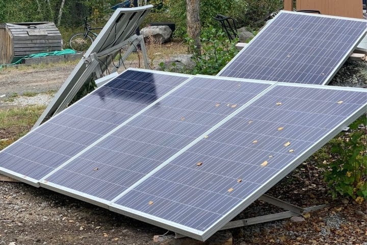
Place it anywhere
A monocrystalline rigid module with a rated power of 50W usually has a fixed physical size of around 540mm x 510mm and a thickness of approximately 30mm. This specification can be easily embedded on a 1.5 square meter balcony railing or the edge of a 0.8 square meter RV roof window.
If you choose an ETFE flexible panel with a thickness of only 2mm to 3mm, its 30-degree bending arc allows it to fit on curved surfaces with a radius of 500mm, such as RV roofs or tent canopies. This installation method can reduce wind resistance by 95%.
In terms of self-weight, small panels usually weigh between 1.2 kg and 3.5 kg, which allows installers to avoid using complex brackets with a load-bearing capacity exceeding 10 kg. Only four stainless steel M6 bolts with a diameter of 10 mm are needed to maintain stability under a driving wind pressure of 120 km/h.
For temporary off-grid scenarios, using four strong magnetic mounts with a pull force of 25 kg can fix the panel to a steel roof with a thickness of 0.8 mm or more within 30 seconds without damaging the paint coating on the surface.
Easy mounting
Adjusting the angle is the core variable for improving power generation efficiency. The bracket design for small modules usually supports a full range of tilt from 0 degrees to 90 degrees.
In areas between 30 degrees and 45 degrees north latitude, adjusting the panel installation angle to 35 degrees can provide about 18% more daily average effective sunlight time than flat installation.
The mainstream Z-type aluminum alloy brackets on the market currently have a total weight of about 180 g per set of 4 pieces, providing a 25 mm ground clearance. This gap can increase the air velocity at the back of the panel by 1.5 m/s, thereby reducing the module's operating temperature by 10°C to 15°C when the ambient temperature is 35°C.
According to semiconductor physics, for every 1°C increase in temperature, the output power will decay by 0.35% to 0.45%. Therefore, this 25 mm installation gap can directly recover about 5% of power loss.
If you are using foldable support legs, the support arm length is usually between 20 cm and 40 cm. By changing the support holes, quick switching between 15 degrees, 30 degrees, and 45 degrees can be achieved, ensuring that an output efficiency of over 85% is still maintained even when the solar altitude angle is only around 20 degrees on the winter solstice.
Sufficient cable length
Small solar panels usually come with 0.9 meter to 1.2 meter long 12 AWG or 14 AWG cables. The MC4 connectors at the ends typically have a contact resistance of less than 0.5 mΩ and a waterproof rating of IP67, allowing them to be placed in one meter of water for 30 minutes without leakage.
In a 12V off-grid system, if the installation position needs to be extended by 5 meters, it is recommended to use copper core wires with a cross-sectional area of 4.0 mm². This can control the line voltage drop within 0.2 V, with power transmission losses below 2%.
If thin wires with a cross-sectional area of only 0.75 mm² are incorrectly used, the heat generated by a 5.5 A current load will cause the terminal voltage to drop by more than 1.5 V, and the charging speed will slow down by 20% to 30%.
For multi-panel parallel installation, using one-to-two Y-branch connectors can increase the total current of two 100W panels from 5.5A to 11A without increasing wiring difficulty, while keeping the operating voltage constant at around 18V.
Identify the direction
Since the light-receiving area of small panels is limited, for every 15-degree increase in the azimuth angle deviation during installation, the power generation will decrease by about 3.5%.
In actual installation, using a compass to face the panel directly south (180 degree direction) with a deviation controlled within 5 degrees ensures that more than 70% of the daily electricity is obtained during the 4 golden hours from 10:00 to 14:00.
For situations where the panel can only be installed on east-facing or west-facing walls due to geographical constraints, the power generation will be 30% to 50% less than south-facing installation. In this case, an additional 40% of installed capacity is needed to compensate for the deficit.
If there is 5% partial shading (such as branch obstruction) in the installation environment, the bypass diodes inside the monocrystalline module will intervene. Although this prevents hot spot effects of over 80°C, it still causes the output voltage of the entire series circuit to drop by more than 30%.
Therefore, when choosing an installation point, ensure that there are no obstructions higher than 1 meter within 3 meters of the panel.
Easy to assemble and disassemble
Portability is an important feature that distinguishes small off-grid modules from rooftop distributed systems. The disassembly cycle is usually controlled within 5 minutes.
For 28W folding bags used for hiking, the PET encapsulation material used has a wear resistance of over 500 cycles. In the unfolded state, it is hung on the back of the backpack through four metal rings with a diameter of 5 mm, using the movement of the back during walking to obtain multi-angle scattered light.
On camping vehicles, using 3M VHB 4,910 high-strength double-sided adhesive tape with a shear strength of 480 kPa can fix flexible panels of about 1.5 kg without drilling, and the adhesive will not fail at 90°C high temperatures.
This drill-free installation method is very friendly to renters or temporary monitoring stations. The adhesive residue left on the surface after disassembly can be cleaned within 2 minutes with only 10 ml of alcohol without any permanent damage.
Cell compatibility
The final step of installation is matching with energy storage equipment. The current generated by small panels is usually managed by 10A or 20A PWM/MPPT controllers.
A 100W panel outputs about 5.5A of current under peak sunlight. It is most scientific to adapt it to a set of 12V 50Ah (about 600Wh) LiFePO4 batteries. At 80% depth of discharge, it takes about 1.5 standard 5-hour sunlight days to fully charge this cell pack.
If the cell capacity is too small, such as only 12V 10Ah, the 5.5A charging current will lead to a charging rate (C-rate) of 0.55C.
This exceeds the recommended 0.1C charging intensity for some lead-acid batteries, causing the cell's internal resistance to increase by 20% within 3 months and shortening its lifespan by 500 charge-discharge cycles.
Conversely, if the cell capacity is as high as 200 Ah, a single 100 W panel can only supplement 4% of the power daily, which cannot offset the controller's own static consumption of about 20 mA. The system will remain in a state of power deficit for a long time.
Power Demand Matching
Calculate consumption
The first step in an off-grid system is to quantify the average total daily power consumption (Total Daily Wh) of all loads.
Taking a typical mobile office scenario as an example: a phone with a built-in 5,000mAh (about 18.5Wh) cell charged 2 times daily requires 37Wh; a laptop with 65W power running for 4 hours consumes 260Wh; plus two 5W LED emergency lights for 5 hours consumes 50Wh. The total base consumption reaches 347 Wh.
In an RV environment, the consumption of a 45W compressor refrigerator at a 25% environmental duty cycle also needs to be added, which is about 270Wh per day.
Adding these data together, you get a daily average demand benchmark of 617Wh.
This figure is not the final installation standard because the depth of discharge (DoD) of lead-acid batteries is usually limited to within 50%, while LiFePO4 batteries can reach 80% to 90%. To maintain a cycle life of more than 3000 times, it is usually recommended to configure the initial energy storage capacity at 1.25 to 1.5 times the daily average power consumption.
Calculation Formula Reference: Daily Consumption (Wh) = Equipment Power (W) × Operating Time (h); Recommended Cell Capacity (Wh) = Daily Consumption ÷ Depth of Discharge Coefficient (0.8).
Don't miss the losses
In the transmission chain from solar panels to batteries to loads, the energy conversion efficiency is not 100%.
Using a traditional PWM controller, the conversion efficiency is usually between 70% and 75%, which means a 100W panel can actually only output about 75W of effective charging power.
In contrast, an MPPT controller with maximum power point tracking can increase this ratio to 94% to 98%.
In addition, if the system involves a 12V DC to 220V AC inversion process, the standby current of the inverter itself is usually between 0.5A and 1.2A. Even if no appliances are connected, it will consume 150Wh to 300Wh of power daily for nothing.
Adding the 2% to 3% voltage drop loss generated by cables at 5A current, the comprehensive energy Performance Ratio (PR) of the entire system is usually only 0.65 to 0.75.
This requires that when matching power, the base consumption of 617Wh must be divided by the comprehensive efficiency coefficient of 0.7, resulting in an actual required panel output of around 881Wh.
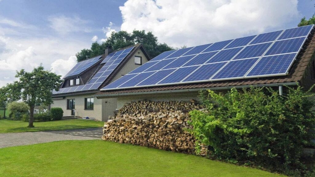
How big should the panel be
Matching panel power requires reference to the average daily peak sun hours at the installation location.
In most mid-latitude regions, the annual average sunlight is about four hours, which means a 100W monocrystalline silicon panel can produce about 400Wh of raw electricity per day.
For the aforementioned demand of 881Wh, you need at least 220W of rated installed power to maintain a balance of payments.
Considering that about 20% of the year is cloudy or rainy, a redundancy coefficient of 1.3 to 1.5 is usually introduced to ensure the system does not crash for 2 consecutive days without light.
Calculated as 220W × 1.5, a 330W panel array (e.g., 3 panels of 110W in parallel) can ensure an electricity surplus in most seasons.
This redundancy is not only to deal with bad weather but also to compensate for the physical attenuation of monocrystalline modules as temperature increases (power drops by 0.39% for every 1°C increase) and surface dust accumulation (drops by 5% to 10%).
Key Parameter Indicators: Peak Sun Hours 4 h; System Redundancy Coefficient 1.5; Temperature Reduction Factor 0.9.
Cell must keep up
The cell capacity and the charging/discharging rate (C-rate) of the panel power must be strictly matched to prevent electrochemical damage.
For a set of 12V 100Ah (1,200Wh) LiFePO4 batteries, the standard recommended charging current is usually 0.2C, which is 20A.
If you are equipped with a 400W panel array, the output current at 18V working voltage is about 22A, which is exactly within the cell's optimal power reception range.
If the cell capacity is too small, such as only 12V 20Ah, the 22A input current will cause the charging rate to soar to 1.1C, causing the internal chemical reaction of the cell to be too intense and the electrolyte temperature to quickly exceed 60°C. This will not only trigger the BMS protection shutdown but also cause the cell capacity to decay by more than 30% within 100 cycles.
Conversely, if the cell capacity is too large (such as 400 Ah) while the panel is only 100 W, the 5.5 A daily supplement cannot even cover the high self-discharge rate of the large-capacity cell.
The cell will remain in a low power state below 40% for a long time, leading to plate sulfation or permanent performance degradation.
Don't mismatch power
Although small solar systems usually only drive a total of 300W of appliances, if they include a small car refrigerator with a rated power of 80W, the surge power at the moment the compressor starts may reach 5 to 7 times the rated value, i.e., 400W to 560W.
Therefore, the continuous output capability of the inverter should be at least 1.5 times the sum of the normal loads, and the peak load-bearing capability must cover the starting current of the heaviest load.
In a 12V system, a 1,000W inverter will draw nearly 90A of large current from the cell at full load.
This requires the cross-sectional area of the wire connecting the cell and the inverter to be at least 25 mm², otherwise the heat loss generated by the line will cause the input voltage to drop below 10.5 V, triggering the inverter's undervoltage protection alarm.
Safe Operation Thresholds: Inverter Continuous Power ≥ Total Load Power × 150%; Starting Peak Power ≥ Maximum Inductive Load Power × 500%.
Environmental Adaptability
Temperature influence
The performance of small solar modules in high-temperature environments is directly subject to their power temperature coefficient (Pmax Temperature Coefficient).
Standard monocrystalline silicon modules calibrate power under Standard Test Conditions (STC) of 25°C, but in actual outdoor direct sunlight, the internal temperature of the solar cells usually soars to 45°C to 65°C.
For most small panels, the temperature coefficient is distributed between -0.35%/°C and -0.45%/°C.
This means that when the solar cell temperature reaches 65°C, compared to the standard environment of 25°C, the panel's output power will decay by about 14% to 18%.
If a 100W panel is working at this time, its actual peak output may only be 82W to 86W.
To alleviate this physical heat loss, the choice of backplane material is crucial.
A backplane using a TPT (Tedlar-PET-Tedlar) three-layer structure has better heat dissipation performance and moisture barrier rate (less than 1.5g/m²/day) than ordinary single-layer PET, allowing the module to work continuously for more than 2000 hours at an extreme high temperature of 70°C without delamination or debonding.
Temperature Index | Parameter Details | Impact on Output |
Normal Operating Cell Temp (NOCT) | 45°C ± 2°C | Power calibration baseline environment |
Power Temp Coefficient (Pmax) | -0.38%/°C | Power drops by 0.38% for every 1°C rise |
Voltage Temperature Coefficient (Voc) | -0.30%/°C | High temperature leads to a drop in open circuit voltage |
Limit Tolerance Temp | -40°C to +85°C | Range where physical structure is not damaged |
Cold resistance
Due to the physical properties of semiconductor materials, for every 1°C drop in ambient temperature, the open-circuit voltage (Voc) of the module rises by about 0.3%.
In the severe winter of -20°C, a panel with a rated Voc of 22 V may actually see its voltage jump to over 25 V.
This requires the matched controller to have at least a 20% voltage margin, otherwise the high voltage will break down the low-end controller capacitors with a 30V voltage tolerance rating.
In terms of physical structure, the tempered glass used in small rigid panels has usually undergone a 2.4 kPa wind load test and a 5.4 kPa snow load test, which is sufficient to withstand the weight of 30 cm thick snow.
For folding panels, the TPU or ETFE encapsulation materials used must still maintain a certain toughness at -40°C.
If the material molecular chains become brittle at low temperatures, repeated folding more than 10 times will result in visible cracks, leading to moisture infiltration and oxidation of the internal busbars, causing the resistance to surge from 0.05Ω to over 10Ω, eventually leading to circuit failure.
Waterproofing
Waterproof performance is the physical bottom line for the long-term reliability of off-grid modules, mainly determined by the IP rating of the Junction Box and connectors.
Professional small solar panel junction boxes usually reach an IP67 rating, which means they can be immersed in one meter of water for 30 minutes without water ingress.
The bypass diodes integrated inside the junction box can not only handle shading issues but also prevent damage to the encapsulation materials caused by the thermal effect of reverse current when the ambient humidity exceeds 95%.
For small modules deployed in seaside or high-humidity forest environments year-round, salt spray corrosion is the main threat.
Modules that pass the IEC 61,701 salt spray test have aluminum alloy frames that have undergone anodic oxidation treatment of more than 15 μm, which can effectively resist the erosion of metal structures by chloride ions.
If ordinary aluminum without anti-salt spray treatment is used, under the sea breeze with a salt content of 3.5%, the frame will show white spot-like corrosion within 12 months, leading to a 30% decrease in mechanical strength and even causing the glass panel to detach from the frame.
Protection/Tolerance Index | Standard Value | Environmental Suitability Description |
Waterproof Rating (J-Box) | IP67 / IP68 | Completely dustproof, short immersion is fine |
Hail Impact Resistance | 25mm Hail @ 23 m/s | Resists conventional extreme weather impacts |
Max Static Load (Front) | 5400 Pa | Capable of carrying about 550 kg/m² of snow |
Salt Spray Corrosion Grade | Level 6 | Suitable for seaside and high-salinity areas |
Wear resistance
The surface encapsulation material of a small panel determines its photoelectric conversion efficiency retention rate and service life. The two currently mainstream encapsulation processes are PET lamination and ETFE coating.
PET material's light transmittance is usually between 88% and 91%, but its hardness is low, with a Mohs hardness of only 2 to 3, making it very easily scratched by fine sand and stones.
When used in a desert environment with high sand and wind for six months, the fogging phenomenon caused by wear on the PET surface will lead to light scattering, reducing the effective irradiance entering the solar cells by more than 15%.
In contrast, ETFE (ethylene-tetrafluoroethylene copolymer) material has a light transmittance as high as 95% and extremely strong anti-ultraviolet (UV) properties. Under strong outdoor UV radiation, its Yellowness Index (YI) change over 20 years is less than 3%.
In addition, ETFE has self-cleaning properties; its friction coefficient is extremely low, and dust can be washed away by more than 90% with only 5 mm/h of rainfall at an installation tilt angle of over 15 degrees. This avoids the daily 10% to 25% power generation loss caused by dust accumulation.
Wind resistance
According to Bernoulli's principle, when the wind speed reaches 25 m/s (Level 10 gale), the lift or pressure acting on a 1 square meter panel can reach around 700 N.
For a 50W small panel, although the wind-receiving area is only about 0.3 square meters, if the bracket installation angle is improper and forms a "wind-catching" structure, the instantaneous 200N upward pull force is enough to pull out insecure expansion bolts.
Professional-grade installation solutions suggest that in areas where wind speeds year-round exceed 15 m/s, 6063 aluminum alloy brackets with a wall thickness of no less than 2.0 mm should be used, ensuring a 20 mm to 50 mm air pressure relief gap between the back of the panel and the installation plane.
This can not only reduce the solar cell temperature through air convection but also reduce the pressure difference between the front and back of the panel by 40% when strong winds sweep across, preventing micro-cracks in the monocrystalline silicon wafers caused by long-term mechanical stress amplitude.
Adapting to the environment
In plateau areas with an altitude of over 2000 meters, the atmospheric pressure decreases, and air thinning leads to a decrease in heat dissipation efficiency. The rated current of the controller needs to be derated by 10% to 20%.
At the same time, the UV intensity in high-altitude areas is 30% to 50% higher than in plains, which accelerates the aging of plastic wire slots and cable jackets, causing them to crack within 3 to 5 years.
Therefore, in scenarios above 3,000 meters altitude, specialized UV-resistant photovoltaic DC cables complying with the UL 4,703 standard must be selected.
For areas where the ambient temperature fluctuates between -10°C and 40°C year-round, it is recommended to be equipped with a controller with a Temperature Compensation function.
Use a compensation coefficient of -3 mV/C/Cell to correct the cell's termination charge voltage, ensuring the cell can be fully charged in winter (not lower than 14.4 V) and not overcharged in summer (not exceeding 13.8 V), thereby maintaining a system design life of 5 to 8 years.