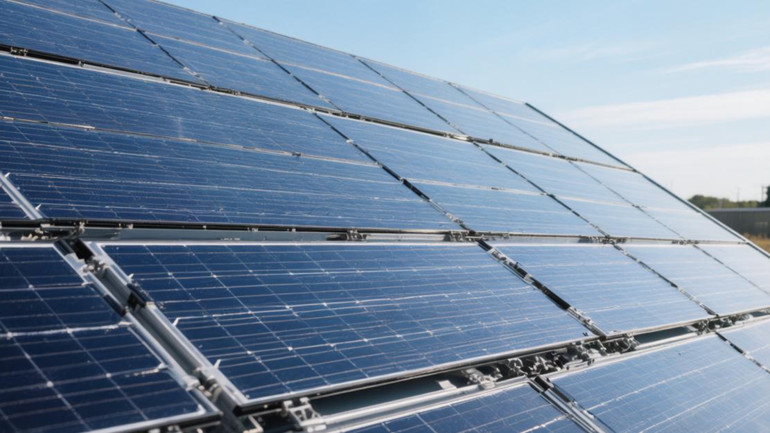
What Are Modular Solar Panels | Design Structure, Flexibility
Modular solar panels are systems that combine multiple small solar units into modules.
Each module usually consists of 60-72 solar cells, with power ranges varying from 250W to 400W.
Modular design makes installation more flexible, allowing adjustment of panel numbers according to needs, adapting to different spaces and usage scenarios, and improving system scalability and maintainability.
Design Structure
Top Layer Glass
The outermost layer of modular solar panels uses 3.2mm thickness low-iron tempered glass, with light transmittance stabilized between 91.5% and 93.8%. One square meter of this glass weighs about 8.5 kilograms, and the surface is coated with a 100 nm to 150 nm anti-reflection coating, which can reduce light reflectivity by 2.5% to 3.0%.
In the impact resistance testing stage, this protective shell can withstand a 25 mm diameter, 227 g weight hailstone hitting vertically at a speed of 23 meters per second. The glass Mohs hardness reaches above level 6, capable of controlling the light transmittance decline ratio caused by sand and dust scratching to within 0.15% per year. The working temperature range covers minus 40 degrees Celsius to 85 degrees Celsius, and within this temperature difference range, the thermal expansion coefficient is maintained at 0.000009 per degree Celsius.
· Glass light transmittance after 10 years of use decreases by less than 1.2%, and the 25-year total light transmittance loss is controlled within 3.5%.
· The anti-static coating can, in an observation cycle of 30 days, reduce surface dust accumulation thickness by about 40%.
· The front can withstand a maximum of 5400 Pascals static snow load, and the back can withstand 2400 Pascals wind load pressure.
Sandwich Layer
Below the glass is an EVA film layer with a thickness of about 0.45 mm, light transmittance is maintained above 90%, and the thermal curing degree is stable between 75% and 85%. Inside the film layer are wrapped 144 or 156 half-cut monocrystalline silicon cells, and the side length of a single cell is mostly 182 mm or 210 mm. Single cell thickness has decreased from 170 microns to 130-150 microns over the past five years, and silicon material consumption has dropped by 15%.
Mass-produced N-type TOPCon cells have reached photoelectric conversion efficiency of 24.5% to 25.2%, which is 1.5 to 2.2 percentage points higher than traditional P-type PERC cells. Under 1000 watts per square meter light intensity and 25 degrees Celsius temperature, a single cell's working voltage is about 0.6 volts, and short-circuit current can reach 13 amperes to 18 amperes.
· N-type cells' first-year light-induced degradation rate is less than 1.0%, and the annual average degradation rate from year 2 to year 30 is about 0.4%.
· The back side of the double-glass bifacial structure can absorb environmental reflected light, bringing 5% to 25% extra power generation gain.
· The power temperature coefficient is approximately negative 0.30% per degree Celsius; for every 1 degree Celsius increase in temperature, output power only decreases by 0.30%.
Water-blocking Backsheet
The bottom-most layer of the module uses a composite fluoroplastic backsheet, with thickness between 0.3 mm and 0.35 mm and weight about 0.35 kilograms per square meter. The backsheet's water vapor transmission rate is below 1.5 grams per square meter per day, capable of reducing the probability of internal cell moisture short-circuiting by 85%. In pressure resistance tests, this insulation sheet can withstand system DC voltage of 1000V to 1500V, and partial discharge voltage is greater than 1000V.
Light reflectivity on the inner side of the backsheet is as high as 88% to 92%, capable of reflecting back the light that penetrated the cells for secondary use, increasing overall module short-circuit current by 2% to 3%. Peel strength tests show the bonding force between the backsheet and EVA film is greater than 40 Newtons per centimeter, persisting for 1000 hours without delamination in a test environment of 85 degrees Celsius and 85% relative humidity.
· Backsheet thermal conductivity is about 0.2 to 0.3 watts per meter Kelvin, capable of reducing module operating temperature by 2 to 3 degrees Celsius.
· After receiving 60 kWh per square meter of ultraviolet irradiation, the backsheet yellowing index change value is less than 3.0.
· Longitudinal tensile strength is greater than 100 MPa, transverse tensile strength is greater than 90 MPa, and elongation at break exceeds 100%.
Aluminum Alloy Frame
One frame with a length of 1.7 meters weighs about 1.2 kilograms, yield strength reaches 110 MPa to 220 MPa, and tensile strength exceeds 150 MPa. The aluminum alloy surface is covered with an oxide film with a thickness of 15 microns to 20 microns, which can last 600 hours in salt spray corrosion tests without rust appearing on more than 1% of the area. There are 8 to 12 elliptical installation holes with dimensions of 9mm by 14mm reserved on the frame, and hole distance error is less than 0.5mm. Silicone sealant with a width of about 8mm to 10mm is filled at the assembly gaps of the four corners of the frame, and gap tolerance is controlled within 0.3mm.
· The bottom frame has 4 to 6 water drainage holes with a diameter of 5 mm distributed, and the rain drainage speed can reach 50 ml per minute.
· The conduction resistance measurement value from the 2 reserved grounding hole positions to any point on the frame is always less than 0.1 ohm.
· Under a load of 2400 Pascals pressure, the deflection deformation at the center of the frame does not exceed one percent of the diagonal length.
Wiring Box
Installed above the backsheet is a junction box with a protection level reaching IP68, volume is approximately 110mm by 110mm by 25mm, and internal potting with 30g to 50g of high thermal conductivity silicone. Two pure copper photovoltaic dedicated cables with lengths of 300 mm to 1200 mm are led out from the junction box, with a core cross-sectional area of 4.0 square millimeters. The cross-linked polyolefin insulation layer wrapped on the outer layer of the cable has a thickness of 0.8 mm, the maximum operating current can withstand 30 amperes, and the resistivity is lower than 4.95 ohms per kilometer.
Three Schottky bypass diodes with rated currents of 15 to 20 amperes are welded inside the box, and forward voltage drop is only 0.4 volts to 0.45 volts. When one-third of the module's area is blocked by shadows, the corresponding area's diode will conduct within 0.1 seconds, controlling the overall power output loss within 33%.
· Junction box shell material reaches UL94-V0 flame retardant grade, extinguishing within 30 seconds under 850 degrees Celsius glow wire contact.
· The junction box can be continuously immersed in 1.5 meters of water depth for 30 minutes, and the internal water ingress detection result is 0 ml.
· Terminal connector insertion and extraction force is between 40 Newtons and 80 Newtons, and contact resistance is less than 0.3 milliohms, ensuring plug-in connection does not loosen for over 25 years.
Flexibility
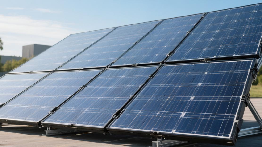
Can Be Installed Anywhere
The single piece area of modular modules is 1.9 square meters, weight is between 20 kg and 22 kg, and structural load per square meter only increases by 10 kg to 11 kg, adapting to pitched roofs with 15 to 60 degree tilt angles, flat roofs, and 90 degree vertical apartment balconies. The balcony installation system adopts aluminum alloy hooks, adjustable width span is between 50 mm and 150 mm, using 4 stainless steel bolts with 8 mm diameter and 60 mm length for fixation; a single adult using 1 torque wrench can complete the suspension of 2 pieces totaling 800 W modules within 45 minutes.
The contact surface between the hook and the railing is equipped with a 3mm thickness EPDM rubber pad; while providing friction force greater than 50 Newtons, it can maintain an elastic recovery rate of over 95% in temperature changes from minus 20 degrees Celsius to 60 degrees Celsius. When the system bracket undergoes wind tunnel testing, under windward side gusts of 30 meters per second, structural deformation is lower than 4 mm, and the value displayed by the stress tester at the connection remains below 50 MPa, far lower than the 150 MPa yield threshold of aluminum alloy.
· The load-bearing limit of balcony iron railings is usually 200 kg; hanging 2 pieces totaling 44 kg modules plus an 8 kg micro-inverter, the total load only accounts for 26% of the railing's safety capacity.
· The thickness of 4 pieces of 100W flexible modules installed on a leisure RV roof is 2.5 mm, each weighing only 1.9 kg, and the wind resistance coefficient increment generated at a vehicle speed of 120 km/h is less than 0.02.
· Ground bracket installation solution ground clearance is generally set to 500mm to 800mm, bottom air circulation increases by 0.5 cubic meters per second, can make the module back working temperature drop by 3 to 5 degrees Celsius, correspondingly improving photoelectric conversion output efficiency by 1.2% to 2.0%.
Add or Subtract Anytime
A basic micro-grid-tied system starts from a single 400W module plus a 600W micro-inverter, initial material procurement budget is controlled within the $350 to $450 range, and floor area only requires 2 square meters. When electricity load increases from 5 kWh per day to 15 kWh per day, users can, in any cycle of 30 days, purchase modules of the same specification to connect in parallel to the original system, expanding total installed capacity from 400 W to 3200 W, with expansion time not exceeding 120 minutes. Newly added modules are daisy-chained via a 2 m length, 4.0 square millimeter cross-section PV AC trunk cable; every added node generates 0.1 ohm contact resistance, and the line loss rate always remains below 1%.
In the ROI model calculation, the initial sunk cost of a 5 kW traditional centralized system is as high as $5,000; adopting a phased modular deployment of a 3 kW system reduces first-year expenditure by 40%, and adding capacity on demand within 3 years can improve capital turnover by 25%, with LCOE long-term maintaining between $0.08 and $0.12.
· Micro-inverters support 1-in-1, 1-in-2, or 1-in-4 input configurations, MPPT maximum power point tracking voltage range is between 22V and 60V, and start-up voltage is as low as 20V, extending daily power generation working time by 40 to 60 minutes.
· Expanding by 4 pieces of 400W modules can increase total daily power generation by 6.5 to 7.5 kWh; calculated at a price of $0.15 per kWh, it saves an additional $30 to $34 in monthly electricity bills.
· DC coupling expansion for energy storage cell packs starts from 5.12kWh modules, maximum allowable parallel connection of 15 cell packs reaches 76.8kWh total capacity, and charge/discharge rate is adjusted in the 0.5C to 1C range.
Fear of Shading?
In a 4000W system composed of 10 pieces of 400W modules, if 1 module is covered by a 0.5 square meter leaf shadow, the overall working current of a traditional series system will plummet from 13A to 3A, instantly causing a power drop as high as 1200W to 1600W. The modular system configures an independent MPPT channel for each module; 0.5 square meters of partial shading only causes that single module's power to drop by 150W, while the remaining 9 modules maintain 3600W full-load output, and the system's overall power generation recovery ratio reaches over 90%.
When local hotspot effects cause the cell temperature to soar to 85 degrees Celsius within 10 minutes, 3 built-in bypass diodes conduct within 0.05 seconds, bypassing the 15A current around the blocked area, suppressing local maximum temperature below 65 degrees Celsius. There is a 3% to 5% factory power tolerance between modules; the independent operation mechanism allows 405W modules and 395W modules to run at full speed in the same system, eliminating the 2% to 4% power loss brought by the short-board effect.
Evaluation Parameter | Traditional Series System | Modular System | Data Difference Rate |
10% area shading power loss | 800W - 1200W | 35W - 45W | Decrease 95% - 96% |
Hot spot maximum physical temperature | 95°C - 105°C | 55°C - 65°C | Decrease 38% - 42% |
Low light startup voltage threshold | 150V - 200V | 20V - 25V | Decrease 86% - 87% |
Annual power gain in lush tree areas | 3500 kWh - 4000 kWh | 4200 kWh - 4800 kWh | Increase 18% - 22% |
Carry and Go
A 2400W system including 6 modules and matching micro-inverters weighs about 145 kg; 2 adults relying on 1 hex wrench and 1 Phillips screwdriver can complete 1 within 60 minutes, ensuring module flatness within 2 mm during installation.
The junction box is located on the back, the size is generally 120 mm × 80 mm, and the internal contains 3 bypass diodes, each diode bearing current at around 15 A. When the module is partially shaded (e.g., 10% area), the bypass diode will automatically conduct, isolating the affected area, so that the power loss of the entire module can be reduced from 30% to 10%-15%. Junction box protection grade is usually IP67, and can maintain 30 minutes in 1 meter water depth without water ingress.
Module output is connected through MC4 interfaces, cable length is generally 1.2 m-1.5 m, wire diameter is 4 mm² or 6 mm², and resistance is controlled within 5 mΩ per meter. Under 10A current conditions, line loss is about 0.5%, which has a small impact on overall system efficiency. Interface design life can withstand 1000 insertions and extractions within a 25-year cycle, and contact resistance remains stable below 0.5 mΩ for the long term.
Looking at the overall structure, the area of a single module is about 1.8 m², and the power generation capacity per unit area is between 200 W-230 W. In a 10 kW system, about 18-22 modules are needed, with a total floor area of about 35 m² -45 m². In an area with an average annual irradiation of 1200 kWh/m², such a system's annual power generation can reach 11000-14000 kWh, and system efficiency (from sunlight to electricity) is overall between 17%-19%.
Structural design also considers thermal expansion issues; the expansion coefficient difference between glass and aluminum frame is about 5×10⁻⁶/℃; in a 40°C temperature difference situation, the length change is about 0.3 mm, and this change is absorbed through reserved gaps in the frame, avoiding internal stress concentration. Long-term testing shows that in a 25-year cycle, the failure rate caused by structural stress is lower than 2%.