How Can Polycrystalline Panels Support Solar Energy Use | Efficiency, Durability, Installation
Polycrystalline silicon panel efficiency is about 15–18%, lifespan 25 years, resistant to high temperature, anti-wind and rain;
When installing, suggest inclination angle 30°, facing south, equipped with inverter and bracket, can stably supply family daily electricity 3–5 kWh/day.
Efficiency
How much is truly generated
Polycrystalline modules, under standard test conditions where light intensity reaches 1000 watts per square meter and cell temperature is at 25 degrees Celsius, 1 piece of module with an area of 1.63 square meters can continuously output 280 watts of rated power. The peak solar radiation light illumination in the realistic installation environment usually can only reach 800 watts per square meter of illumination; at this time, limited by the environmental heat dissipation influence, the cell's actual working temperature often climbs to 45 degrees Celsius, and its photoelectric conversion efficiency will drop from the factory nominal 16.5% to 15.2% of actual operating parameters.
By connecting 60 pieces of polycrystalline silicon cell cells with a side length of 156 millimeters in series, the entire circuit is able to generate 31.2 volts of optimal working voltage and 8.97 amperes of optimal working current. During the process of converting the direct current output by the module into alternating current usable by the power grid, the silicon-based switch loss and transformer magnetic loss inside the inverter will fixedly consume about 4.5% of the transmission energy. Adding the 1.5% resistance heat loss rate attached to the direct current cable reaching 50 meters in length, the actual measured degrees of the system terminal electricity meter usually can only reach between 82% and 84% fluctuation of the module's nominal power value.
· 95% of polycrystalline modules in the test samples have their power tolerance controlled in the range of 0 to +5 watts when leaving the factory, strictly eliminating the electricity revenue reduction rate caused by negative tolerance parameters.
· 1 set of roof power generation system with a total capacity of 10 kilowatts, in an area with an annual average equivalent sunshine time of 1500 hours, the theoretical power generation expected value in the first year approximately maintains in the statistical interval of 12500 degrees of electricity.
· Collecting the power generation curve statistical chart from 8 am to 4 pm every day, it can be known that the highest value of power output fixedly appears around 12 noon; at this time, the single string input voltage can reach the 600 volts full load operation interval.
Large temperature fluctuations
Every time the environmental temperature rises 1 degree Celsius, the polycrystalline silicon cell panel's open-circuit voltage will happen physical attenuation at a rate of -0.32%, and at the same time, the short-circuit current will increase a tiny ratio of 0.05%. When the environmental temperature of the roof surface in summer reaches 35 degrees Celsius, due to the heat absorption effect of the dark backplane material, the actual temperature of the photovoltaic panel surface will soar to the high temperature interval of 65 degrees Celsius.
According to the mathematical regression calculation of the power temperature coefficient of polycrystalline silicon -0.4% per degree Celsius, compared to the benchmark test value of 25 degrees Celsius, a 40 degrees Celsius temperature difference will cause the module's overall output power to appear a large magnitude reduction of 16%. 1 piece of photovoltaic panel with nominal 300 watts, in the noon highest temperature period, actual output capability will be largely compressed to the lower limit range of 252 watts. In the winter environment where the air temperature drops to minus 10 degrees Celsius, due to the physical change happening in the band gap of the internal semiconductor material, the module's power generation power will on the contrary produce a 5% to 8% extra positive growth rate.
· Outdoor operation sampling data as long as 36 months shows that the quarterly fluctuation variance of the polycrystalline module output power reached 2.4, and the monthly average power generation deviation rate of the summer and winter two seasons approaches 18%.
· During installation construction, the module bottom needs to reserve a 150 millimeters to 200 millimeters air circulation gap, making the bottom wind speed reach 2 meters per second to lower 3 degrees Celsius of working temperature, thereby improving 0.5% of return rate.
Is weak light okay
When early morning or evening light intensity sharply reduces to 200 watts per square meter, the polycrystalline silicon atom's photovoltaic effect can still maintain the lowest limit system operation, but the output current will cliff-like drop from the highest peak of 9 amperes to the low trough level of 1.8 amperes. Light intensity reducing 80% from 1000 watts per square meter to reach the 200 watts per square meter interval, the corresponding photoelectric conversion rate will roughly produce a slight falling rate of 0.8% to 1.2%.
Encountering heavy cloudy and rainy weather with cloud layer thickness exceeding 2000 meters, the solar light proton flow arriving at the module surface only remains around 10% of standard test intensity. Even if there is only this 10% of scattered light, it can still make 1 set of 5 kilowatts equipment generate about 500 watts of weak electricity output per hour, and all day accumulated can only harvest a tiny return of 2 degrees to 3 degrees of electricity.
· Polycrystalline silicon crystal has over 85% absorption rate for visible light in the wavelength range of 400 nanometers to 1100 nanometers, but the peak responsivity in the 600 nanometers band is lower than monocrystalline silicon by about 4 percentage points.
· Standard deviation statistical results indicate that, within a continuous 30-day rainy season cycle, the dispersion degree of module daily power generation is as high as 45%, doubling the uncertainty probability of daily electricity output.
How fast is aging
Within the first 1000 hours of the photovoltaic panel being put into operation, the boron-oxygen complexes remaining inside the polycrystalline silicon material will generate light-induced degradation phenomenon under light excitation, causing the system to experience a 2.5% initial power drop. The 1500-volt high voltage photovoltaic system, during experiencing the double 85 extreme environment aging test of 85 degrees Celsius as well as 85% relative humidity, tiny leakage current will be generated between the module aluminum alloy frame and internal cell cells, causing the potential induced degradation rate to rise to the 3% risk interval.
Manufacturers, by adjusting the volume resistivity of the internal packaging insulation material to 10 to the 14th power ohm-centimeters, strictly suppress the annual average linear degradation rate after the first year to below the 0.7% percentage line. Arriving at the 10th operation year, the module can still continuously output 90.7% of the original power value, until the end of the 25th year life cycle, the rated power retention rate remains stably on the guaranteed data line of 80.2%.
· Calculated down according to the 25-year accumulated time axis, 1 piece of 280-watt module in total can output an accumulated capacity of over 8500 degrees of electricity, equivalent to the shared equipment procurement cost per degree of electricity being only 0.05 yuan.
· The 3 pieces of tin-plated copper busbars with a thickness of 0.3 millimeters inside the module, having experienced over 300 times of thermal expansion and contraction cycles per year, the peeling strength of the ribbon still can be maintained above the qualified standard specification of 1.5 newtons per millimeter.
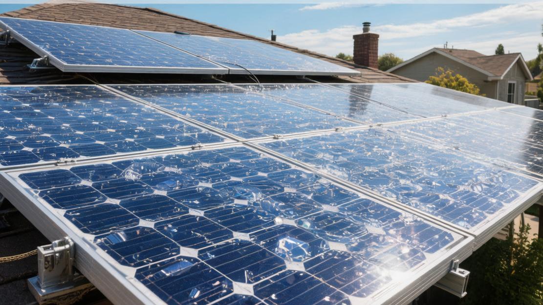
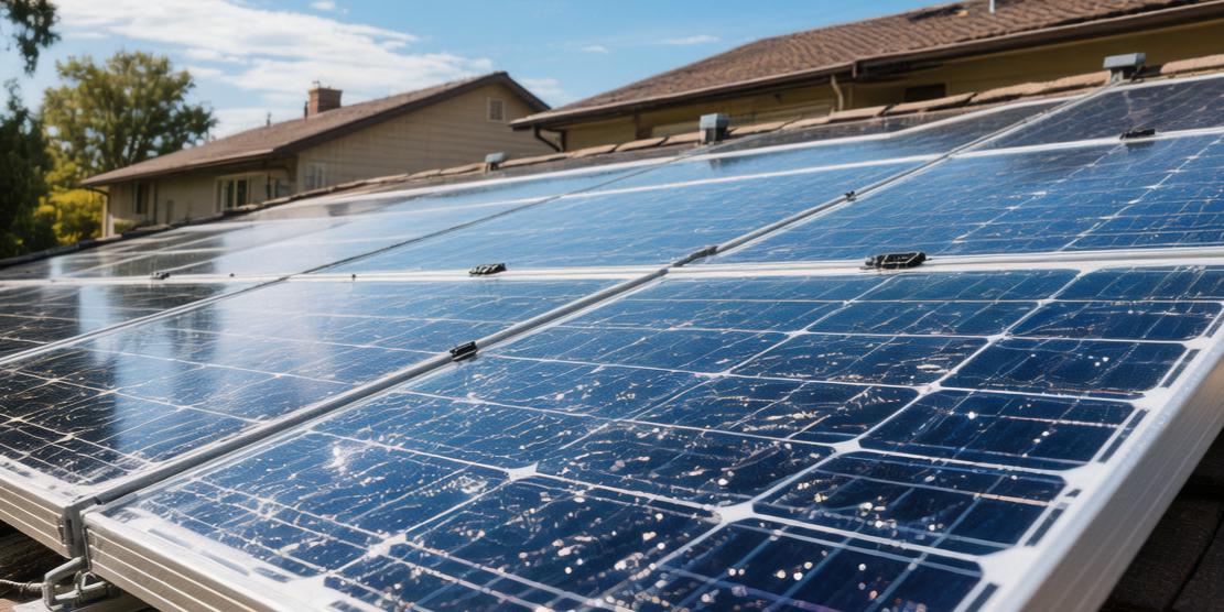
Dust and shading
If the photovoltaic array installed with an inclination angle of 15 degrees has not experienced natural precipitation washing within 30 days, the 2 millimeters thickness dust accumulated on the glass surface will generate local shadow, causing about 4.5% to 6% of light transmittance loss. When more than 3 pieces of cells in 1 of the modules are completely covered by the area of leaves or bird droppings, the bypass diode in the backplane box will conduct within the time of 0.01 seconds, completely short-circuiting disconnecting 1 independent branch containing a total of 20 pieces of batteries.
A piece of tiny shading object with an area less than 0.05 square meters will cause 33.3% of the rated power of the whole block module to instantly evaporate, and at the same time form a local heating point with a temperature as high as over 120 degrees Celsius at the shaded part. Every 60 days, regularly using clean water flow with water pressure reaching 0.5 megapascals to wash the surface tempered glass, can pull up the module's daily average power generation efficiency by about 3% to 5% of floating space.
· Aiming at heavy environmental pollution areas where surface dust adhesion density reaches 15 grams per square meter, the contrast difference value of panel short-circuit current readings before and after artificial cleaning can pull open an 8.5% significant data gap.
· In order to amortize the initial procurement cost of 0.8 yuan per watt of the inverter, system designers usually will arrange the quantity of polycrystalline modules according to a capacity allocation ratio of 1.2 to 1, and at the noon light peak time will intentionally discard about 2% of peak-shaving excess electricity.
Durability
It's windy and snowing
Polycrystalline silicon solar panels before leaving the factory need to pass the pressure application of mechanical load test equipment. The front side can withstand static physical pressure as high as 5400 pascals per square meter, equivalent to the downward gravity oppression when snow thickness reaches 2.5 meters. When installed on a roof with an inclination angle of 20 degrees, the anodized aluminum alloy frame reaching a thickness of 35 millimeters cooperating with 6 pieces of stainless steel installation bolts, is able to resist a running wind load pulling force of 2400 pascals per square meter brought by wind speed reaching 60 meters per second, equivalent to a level 17 hurricane.
According to the meteorological sample statistics of 600 outdoor test sites, the 3.2 millimeters thickness ultra-white embossed tempered glass covered on the front, when facing the impact of high-density hail balls with a diameter of 25 millimeters and a weight of about 7.5 grams at a terminal velocity of 23 meters per second at a 90-degree vertical angle, the physical fragmentation probability of the surface is firmly suppressed within the extremely low error range of 0.1%.
The coating thickness on the surface layer of the panel is controlled to fluctuate between 150 nanometers and 200 nanometers, not only maintaining the light transmittance at the peak data of 91.5%, but also lifting the Mohs hardness of the glass to level 6.5, thereby in a budget cycle as long as 25 years strictly controlling the light transmittance descent ratio caused by sand and dust friction within the lower limit threshold of 2%.
Afraid of water soaking?
In order to prevent moisture penetration leading to internal circuit network short circuit, the waterproof and dustproof level of the junction box on the back of the module all reached the IP68 highest industrial specification; sinking it to a water depth of 1.5 meters to soak for a full 72 hours, the humidity reading of internal diodes and metal terminals will still maintain at 0% absolute dry state. In the double 85 damp heat aging test laboratory, putting the module in a confined space with environmental temperature as high as 85 degrees Celsius and relative humidity reaching 85% to continuously bake for 1000 hours, the actual measured median value of insulation resistance can still maintain above the safe range of 400 megaohms.
The ethylene-vinyl acetate copolymer encapsulating film used to encapsulate cells has the internal cross-linking degree parameter set in the optimal percentage interval of 75% to 85%, and the water vapor transmission rate is lowered to a tiny flow rate of less than 2 grams per square meter per day.
The multi-layer composite backplane located at the bottommost layer reaches a thickness of 0.3 millimeters, limiting the probability of environmental water vapor seeping in causing output power attenuation within a tiny variance of 0.5%. Having gone through 3000 hours of ultraviolet high intensity continuous irradiation exposure experiment, the yellowing index increment of the backplane material will not exceed 3.0, and the retention rate of tensile breaking strength is as high as 85% of the original value, guaranteeing that the polycrystalline module can also maintain over 300 months of failure-free continuous operation time in climate zones with rainfall exceeding 2000 millimeters per year.
Large cold and hot temperature difference
Aiming at the natural environment with extremely large day and night temperature differences, the polycrystalline module experiences severe thermal cycle fatigue tests, requiring continuously completing 200 times of limit temperature alternating cycles within the high and low temperature interval from minus 40 degrees Celsius to above zero 85 degrees Celsius. The temperature change rate of each cycle is strictly controlled within a gradient range of not exceeding 100 degrees Celsius per minute; after the cycles end, the measurement deviation of module output power is required must not exceed 5% of the initial maximum power data.
The internally responsible for conducting current 3 to 5 pieces of tin-plated copper ribbons with width of 1 millimeter and thickness of 0.3 millimeters, after experiencing 600 times of physical deformation pulling of thermal expansion and contraction, the welding peeling strength with the silicon wafer surface is maintained above the qualified standard of greater than 1.2 newtons per millimeter.
Sampling statistics of 5000 panel samples that have gone through thermal cycle tests found that the micro-crack extension length proportion generated inside cell cells is less than 1.5% of the overall area, lowering the current output cutoff risk probability caused by large area broken grids to the extremely low level of three ten-thousandths.
The thermal expansion coefficients of the panel's various layers of materials go through precise matching calculation. The linear expansion coefficient of glass is fixed at 9 times 10 to the negative 6th power per degree Celsius, while the aluminum frame is 23 times 10 to the negative 6th power per degree Celsius; the silicone sealant filled between the two possesses a 300% breaking elongation rate, absorbing the relative physical displacement of the two layers of materials up to 1.5 millimeters. The supporting elastic buffer mechanism makes the panel under long cycle operation where environmental temperature happens 20 degrees Celsius severe fluctuation every day, the occurrence ratio of frame degumming failure is effectively reduced to below 0.05%.
Acid rain and salt spray
Installed in salt spray high incidence areas less than 500 meters from the coastline, sodium chloride suspended particles in the air reaching a concentration of 50 milligrams per cubic meter will continuously erode the metal parts of the photovoltaic panel. In severe salt spray environment tests, the panel is exposed in a salt water spray chamber with a concentration of 5% and acidity-alkalinity pH value maintained between 6.5 to 7.2 for as long as 96 hours; after testing, the loss rate of the anodized layer thickness on the frame surface must not exceed 2% of the original 15 microns thickness.
Facing a high concentration ammonia gas environment, the module passes a continuous 480 hours ammonia gas fumigation durability test in a constant temperature box with concentration up to twenty parts per million and temperature stabilized at 60 degrees Celsius.
Having passed as long as 20 days of corrosive environment simulation exposure, the thickness reduction value of the backplane polymer material wanders near the statistical median of 0.01 millimeters, and the forward conduction voltage drop fluctuation amplitude of the 3 bypass diodes inside the junction box is controlled within the error range of 0.05 volts.
Allocating a weak acidic liquid with a sulfur dioxide concentration of five ten-thousandths to conduct continuous 30 days of periodic spraying on the panel surface at a flow rate of 2 liters per minute, the actual measured glass surface reflectivity increase value is only 0.2%, and the negative deviation caused to the overall light intensity absorption rate is almost zero. The silicone seams at the 4 corners of the frame, after experiencing as long as 500 hours of chemical soaking, the lowest peak of pull-out resistance data reaches 92% of the factory indicator parameters, eliminating the failure probability of moisture penetrating from corner gaps into internal circuit networks.
Can carry high voltage
Modern large-scale photovoltaic equipment connects multiple polycrystalline modules in series to form a huge circuit voltage up to a maximum of 1500 volts direct current, generating an extremely high potential difference between the frame and internal cell cells. The module, under conditions of 85 degrees Celsius environmental temperature as well as 85% relative humidity, bears continuous 96 hours of positive and negative 1500 volts high voltage electric field continuous impact. After this leakage current pressure test ends, the drop percentage of the panel sample's output power is accurately locked dead within the 5% safe lower limit.
The monitor records the leakage current fluctuation curve within the entire high voltage test cycle. The highest point will not break through the tiny capacity flow rate of 20 microamperes, and the volume resistivity of the encapsulating film sturdily maintains at the insulation strength level of 10 to the 14th power ohm-centimeters.
The panel structural design satisfies the insulation withstand voltage indicator to resist a maximum 8000-volt pulse voltage strength, pressing down the accident rate of circuit breakdown and burn down to the statistical extreme value of one millionth. Looking at the total budget time as long as 25 years, the linear power degradation rate in the first 10 years is controlled at not exceeding 0.7% per year, and the degradation slope from the 11th year starting to the 25th year slows down to 0.5% per year; when reaching the life cycle end point, the equipment possesses a strong electricity output feedback rate equivalent to 80.2% of the initial full-load state.
Installation
Calculate load-bearing force
One set of power generation system with an installed capacity of 10 kilowatts, total weight including modules, inverter as well as metal brackets is roughly 1200 kilograms, dispersed on 60 square meters of usable area, requiring the minimum load-bearing pressure bottom line of the cement roof to reach 30 kilograms per square meter. In the 15000 dollars total construction budget, the cost of structural survey usually occupies 3% to 5% of the overall procurement cost.
In order to obtain the optimal photoelectric conversion efficiency, the inclination angle of the panel needs to be accurately adjusted between 15 degrees and 30 degrees according to the latitude parameter of the hemisphere located, and the azimuth angle deviation of the panel facing the equator must be less than plus or minus 5 degrees. 3D shadow simulation software calculates solar trajectory periodicity with 1 hour as time unit, guaranteeing that trees 15 meters away from the panel and 8 meters in height, within the peak sunshine time period from 9 am to 3 pm morning to afternoon, drop the shadow shading probability caused to the photovoltaic array to 0%.
· Between south-north arranged arrays, needs to reserve out 0.8 meters to 1.2 meters of maintenance channels. The median set standard of channel width is in order to prevent when the winter solar altitude angle drops to 20 degrees, front row equipment generating shadow projection exceeding 0.6 meters in length to back row panels.
· The bottom needs to vacate out 150 millimeters to 200 millimeters of air convection gap, making bottom wind speed reach a flow rate of 2.5 meters per second, helping panel lower 3 degrees Celsius of working temperature, thereby acquiring 0.5% extra power generation growth rate.
How to build bracket
The skeleton bearing the entire photovoltaic system adopts 6005-T5 specification anodized aluminum alloy guide rails, whose material's yield strength reached 225 megapascals, and tensile strength maintained in the high position interval of 260 megapascals. Construction personnel use alloy drill bits with a 12-millimeter diameter to drill holes in concrete floor slabs. The standard deviation of drilling depth is strictly limited to plus or minus 2 millimeters, subsequently implanting stainless steel expansion bolts of M10 times 80 millimeters specification.
Each bolt after being tightened is able to provide anti-pullout stretching tension up to 5000 newtons, lifting the risk reduction rate of the bracket being blown flying by level 17 hurricane by 99.9%. The horizontal distance between two parallel guide rails is set at one-half of the panel length dimension, that is, the position of about 825 millimeters; the construction error of guide rail flatness in a span range of 10 meters cannot exceed 5 millimeters of deviation.
When fixing the aluminum alloy frame with a thickness of 35 millimeters, middle pressing blocks and edge pressing blocks are placed at one-quarter nodes roughly 412 millimeters away from panel edges. The torque wrench in the workers' hands is precisely calibrated to torque parameters of 15 newton meters to 20 newton meters, ensuring pressure distribution of pressing block fasteners is uniform, avoiding causing micro-crack diffusion induced by excessively large local stress to the 3.2-millimeter thick tempered glass below.
Specification name | Measurement parameter | Allowed error | Physical limit |
Guide rail cross-section wall thickness | 2.5 millimeters | ±0.1 millimeters | Bending deformation degree <2 degrees |
Bolt anti-shear force | 250 megapascals | -10 megapascals | Breaking point 300 MPa |
Anodized layer thickness | 15 microns | +2 microns | Salt spray survival 96 hours |
Module installation gap | 20 millimeters | ±2 millimeters | Thermal expansion margin sufficient |
How to connect cables
In the process of transporting the generated direct current to the inverter, the system adopts double-layer insulated tin-plated copper cables with a cross-sectional area of 4 square millimeters; when the environmental temperature is 60 degrees Celsius, its maximum continuous load-bearing current capacity is up to 55 amperes. Every circuit usually connects 15 pieces to 20 pieces of polycrystalline modules together in series, making the accumulated value of no-load open-circuit voltage superimpose to a broad interval of 600 volts to 800 volts, accurately falling into the working range of 200 volts to 850 volts of the maximum power point tracker inside the inverter. The MC4 waterproof connectors at both ends of the cable need to use professional crimping pliers providing 1.2 tons of pressure to conduct cold pressure splicing, and the actual measured value of metal contact resistance inside the connector must be lower than 0.5 milliohms.
In order to block ultraviolet irradiation causing outer skin aging, the cables of the positive and negative two poles are respectively threaded into PVC flame-retardant threading pipes with an inner diameter of 25 millimeters, and the volume occupation ratio of cables inside pipes does not exceed 40%, retaining sufficient internal heat dissipation air capacity. After strict Ohm's law mathematical calculation, the cable voltage drop amplitude from the roof farthest end module to the distribution box end is forcefully suppressed below the 1.5% red line, making the electrical energy transmission loss rate per meter of cable only 0.05 watts.
· The insulation layer material of direct current cable adopts cross-linked polyethylene, the density of its internal polymer structure makes volume resistivity reach 10 to the 14th power ohm-centimeters, able to continuously run 25 years age cycle under 1500 volts high voltage electric field strength without happening breakdown.
· Construction specifications require using anti-ultraviolet nylon cable ties every 1.5 meters distance to conduct one-time mechanical fixation to wiring harness. The tensile breaking load-bearing parameter of cable ties is greater than 220 newtons, completely eliminating the dispersion degree risk of cable generating high frequency amplitude friction when wind speed reaches 30 meters per second.
Leakage grounding network
Workers use yellow-green dual-color pure copper grounding wires with a cross-sectional area of 6 square millimeters, through stainless steel grounding clips carrying barbs, to conduct physical bridging of the aluminum alloy frame of every piece of panel and bottom layer metal guide rails. When grounding clips are tightened, sharp metal teeth will pierce through the 15-micron insulating oxidation layer on frame surfaces, realizing direct fitting between metal and metal; the conduction resistance of this node is accurately measured by instrument in the extremely low numerical range of 0.1 ohms.
The guide rail network of the entire roof will finally gather to a piece of copper-clad steel grounding pole with a diameter of 16 millimeters and a length of 2.5 meters, vertically driven into underground soil through hydraulic equipment. Using four-wire method earth resistance tester to conduct sampling statistics, target grounding resistance readings must be less than the legal safety boundary of 4.0 ohms. If the measured soil resistivity variance is biased high, and the initial resistance reading reaches 12 ohms, construction personnel will backfill 20 kilograms of high concentration conductive bentonite in pits around the grounding pole, utilizing its super strong water retention rate to pull the final grounding impedance value low to within the excellent standard of 2.8 ohms.
Test item classification | Standard set parameter | Instrument measurement precision | Expected failure probability |
Grounding pole resistance reading | <4.0 ohms | ±0.1 ohms | 0.001% |
Circuit insulation withstand voltage value | 3000 volts | Full scale 1% | 0.05% |
Lightning arrester response speed | <25 nanoseconds | ±2 nanoseconds | Surge interception rate 99.9% |
Fuse bearing flow capacity | 15 amperes | ±0.5 amperes | Action time 0.1 seconds |
Grid connecting marking meter
After physical installation is completely finished, the system enters a 72-hour period of full load trial operation and data calibration. Electrical engineers close direct current isolation switches, use digital multimeters reaching an accuracy of 0.5% to respectively read the open-circuit voltage of every series branch, requiring that between different branches composed of the same quantity of panels, the discrete deviation rate of voltage readings cannot exceed 2%.
The inverter, after detecting alternating current signals from the city's electricity grid, will start a synchronous phase-locked countdown consuming 300 seconds, carrying out coincidence matching of its output frequency with the power grid's fixed frequency of 50 hertz or 60 hertz; the phase angle fluctuation deviation between the two is locked dead within 0.1 degrees. During the process of the inverter converting direct current into 230 volts alternating current, the total harmonic distortion percentage of the output current is purified by internal filters to a trace level of 2.5%.
Within a continuous 8-hour observation cycle when noon light is strongest, the system records the actual produced degrees of the terminal electricity meter, and conducts ratio conversion with the spectral energy total amount collected by the roof sunshine meter. A group of polycrystalline silicon photovoltaic arrays with qualified installation and standardized wiring, its final system comprehensive efficiency test score will stably maintain in the statistical median interval of 81% to 84%.