What Makes Monocrystalline PV Panels So Efficient
With its high-purity structure and orderly atomic arrangement, monocrystalline silicon significantly reduces electron recombination loss, achieving commercial conversion efficiencies of 20%-24% and maximizing energy density through precision engineering.
Ultra-High Material Purity
Superior Silicon Purity
Monocrystalline silicon modules demand extremely high raw material cleanliness, typically reaching the 11N level of 99.999999999%.
In contrast, ordinary polycrystalline silicon only requires 6N to 9N purity, with impurity levels over 100 times higher.
In the Siemens purification process, trichlorosilane gas is reduced in a high-temperature furnace at 1,100 degrees Celsius, with deposition rates maintained at 10 to 15 microns per hour.
This process controls the concentration of electrically active impurities such as boron and phosphorus to below 0.1 ppb, with fewer than 5 billion impurity atoms per cubic centimeter of silicon crystal.
When monocrystalline silicon ingots are grown in a pulling furnace at a rate of 1.0 to 2.5 mm per minute, the internal oxygen content is strictly limited to within 12 ppma.
Ultra-low impurity levels ensure that minority carrier lifetimes can reach 2000 to 5000 microseconds, providing the physical foundation for conversion efficiencies exceeding 25%.
· Detailed Purification Parameters:
o Industrial silicon raw material purity ranges between 98.5% and 99.2%.
o After trichlorosilane rectification, metal impurity content drops to below 0.01 ppb.
o Energy consumption in the reduction furnace is approximately 45 to 60 kWh per kilogram.
o The circulation efficiency of the tail gas recovery system is typically set above 99.5%.
o The produced electronic-grade polysilicon chunks have a size distribution between 10 and 100 mm.
Strict Impurity Management
During the 1420-degree Celsius monocrystalline pulling process, even a microscopic dust particle weighing 1 mg falling into the crucible can cause crystal structure dislocations in 300 kg of silicon melt.
The interior of the pulling furnace is filled with high-purity argon at a pressure of 10 to 30 mbar, with a flow rate controlled at 60 to 100 liters per minute to carry away evaporated silicon oxide.
The purity of the quartz crucible must also exceed 99.99%, as 1 to 2 microns of the quartz inner wall dissolve into the silicon liquid every hour.
To combat this contamination, the pulling process employs a magnetic field of 0.5 to 1.5 Gauss to suppress convection in the silicon melt, reducing oxygen concentration fluctuations to within 5%.
The extremely low distribution of impurity concentrations allows the resistivity uniformity deviation of the silicon wafers to be controlled between 3% and 8%.
If the impurity concentration increases tenfold, the short-circuit current of the solar cell will immediately drop by more than 0.5 Amperes.
· Thermal Field Control Data:
o The heater power is usually maintained at 120 to 150 kW.
o The service life of a quartz crucible is only 300 to 400 hours.
o The vacuum leak rate in the furnace chamber must be lower than 0.01 Pa·m³/s.
o Seed crystal rotation speed is set at 8 to 15 RPM.
o Crucible rotation speed alternates between 1 and 5 RPM.
Extended Electron Lifetime
Ultra-high purity reduces the number of recombination centers inside the silicon wafer by more than 90%, allowing electrons to travel longer distances before being collected.
In N-type monocrystalline silicon wafers, the diffusion length of hole carriers can reach 1 mm, which is more than six times the wafer thickness of 150 microns.
More than 99% of the charges excited by sunlight can successfully reach the metal busbars on the cell surface.
If the purity drops to the 7N level, the carrier lifetime will plunge from 3000 microseconds to below 100 microseconds, resulting in a 4 percentage point loss in conversion efficiency.
Under standard test conditions at 25 degrees Celsius, this high-purity material can support an open-circuit voltage of over 710 mV.
For every 0.1 ms increase in carrier lifetime, the corresponding module output power can increase by approximately 1.5 Watts.
· Electrical Performance Comparison:
o The recombination rate of monocrystalline silicon is lower than 10 cm/s.
o Polycrystalline silicon, due to many impurities at grain boundaries, has a recombination rate as high as 1,000 cm/s.
o The internal quantum efficiency of high-purity silicon wafers exceeds 95% in the 300 to 1,100 nm wavelength band.
o Surface recombination loss for 182 mm specification wafers is reduced to below 0.2%.
o For a cell with 22.5% efficiency, its dark current is controlled at 10⁻¹³ A/cm².
Stable Voltage Support
The precision of the resistivity distribution in monocrystalline silicon material determines the module's performance under different lighting conditions, usually controlled between 0.5 and 2.0 Ohm-cm.
By adding milligram-level boron or phosphorus elements to the high-purity silicon liquid, the doping concentration error is limited to about 1%.
This precise concentration control allows the solar cell to maintain a relative efficiency of over 90% even under low light conditions of 200 W/m².
During 25 years of outdoor use, because the internal boron-oxygen pair content is lower than 10¹⁰ pairs, Light-Induced Degradation (LID) can be controlled within 0.5%.
If material purity is insufficient, the first-year power degradation could exceed 3%, causing the return on investment for power plant owners to drop by 1.5 percentage points.
Current mainstream 182 mm monocrystalline silicon wafers weigh about 50 grams each yet can stably contribute over 7.5 Watts of power output.
· Life and Degradation Data:
o The first-year degradation rate for standard P-type monocrystalline is 1.5% to 2.0%.
o The first-year degradation rate for high-purity N-type monocrystalline drops below 1.0%.
o Cumulative power output after 25 years usually stays between 87.4% and 89.4% of the initial value.
o The standard deviation for oxygen and carbon content testing in monocrystalline wafers is less than 0.2 ppm.
o The share of high-purity silicon material in the power generation cost per Watt is approximately 20% to 30%.
Detailed Cost Analysis
Although the price per kilogram of electronic-grade silicon material purified to 11N is 5 to 8 times more expensive than 6N industrial silicon, the system benefits far outweigh the investment.
In a 100 MW photovoltaic power plant, using high-purity monocrystalline modules generates 12 million more kWh of electricity per year than ordinary modules.
Calculated at 0.3 RMB per kWh, the additional annual electricity revenue reaches 3.6 million RMB.
High efficiency resulting from high purity reduces the number of mounting brackets by 15% and shortens cable length by more than 2000 meters.
Based on comprehensive calculations, although the cost per Watt of the module is 0.1 RMB higher, the Internal Rate of Return (IRR) of the power plant can increase from 6% to about 8.5%.
In mass production, the cutting loss of a single wafer is controlled within 10%, and 1 kg of silicon material can yield approximately 60 to 65 wafers of 182 mm size.
Stability Under Extreme Conditions
Excellent Heat Resistance
The temperature coefficient of monocrystalline solar cells typically ranges from -0.3% to -0.35% per degree Celsius.
When the ambient temperature rises from 25°C to 65°C, the output power of the panel drops by approximately 12% to 14%.
In contrast, the loss rate for ordinary polycrystalline modules often exceeds 16%, which allows monocrystalline systems to contribute 5% to 8% more power per hour during the peak periods from 12:00 to 14:00 in summer.
Inside the module, the backsheet material must pass a 1000-hour "Double 85" (85°C / 85% humidity) aging test to ensure power degradation is controlled within 5%.
High-quality monocrystalline modules operating in a 75°C rooftop environment limit the increase in internal series resistance to below 0.2 milliohms.
For every 1°C decrease in cell temperature,
power generation efficiency increases by 0.35%.
The heat dissipation backsheet is 300 microns thick,
improving the heat dissipation rate by about 15%.
To maintain this stability, modules use 3.2 mm thick tempered glass, which will not crack under a temperature differential impact of 250 degrees Celsius.
In laboratory thermal cycle tests of 200 repetitions, the electrical performance fluctuation of monocrystalline modules is only 1.5% to 2.3%.
This temperature resistance directly affects the IRR of the power plant.
In regions with average temperatures above 30°C, the 25-year total power generation revenue of monocrystalline systems is over 10.5% higher than that of polycrystalline systems.
The atomic structure inside each monocrystalline silicon wafer maintains 99.9% chemical stability at temperatures below 100 degrees Celsius.
Heavy Pressure Resistance
Monocrystalline module frames use 6063-T5 hardness aluminum alloy, with thicknesses typically between 30 mm and 40 mm, capable of withstanding a front-side static snow load of 5400 Pa and a back-side wind pressure of 2400 Pa.
This strength ensures that the mechanical deformation rate of the module is below 0.5% under strong winds of 130 km/h.
For extreme hail weather, modules must pass a steel ball impact experiment (25 mm diameter at 23 m/s) to ensure zero cracks on the glass surface and 0% power loss.
In actual installations, using four high-strength M8 bolts ensures the mounting system remains as steady as a rock during a once-in-a-50-year hurricane.
Withstanding 5400 Pa of pressure
is equivalent to 550 kg per square meter.
The aluminum frame tensile strength is 185 MPa,
protecting the silicon wafer from micro-crack risks.
The silicon wafers themselves undergo fine cutting to 160–180 microns, providing a degree of flexibility. When subjected to a dynamic load cycle of 1000 Pa, the probability of an internal electrical path interruption is below 0.01%.
The high-strength EVA encapsulation material has a weight of 450 to 500 grams per square meter, providing excellent buffering performance and reducing the transmission efficiency of external stress to the silicon wafer by more than 90%.
The weight of a single module is generally between 20 and 30 kg. This density design balances structural rigidity with installation load, reducing mounting costs by 15%.
Long-Term Durability
The chemical properties of monocrystalline silicon wafers are very inert.
Their first-year power degradation rate (LID) is controlled within 1.0% after gallium-doping optimization, and the subsequent average annual linear degradation rate is only 0.4% to 0.5%.
Over a service cycle of 300 months, the cumulative power output of the modules usually stays between 87.4% and 89.2% of the initial value.
To combat the PID (Potential Induced Degradation) effect, the module's glass and encapsulation film must have a leakage current of less than 0.1 microamperes per square centimeter under a 1000V high-voltage environment.
This ensures that the system maintains an insulation resistance level of 98.5% during 15 to 20 consecutive rainy days, avoiding a 3% to 5% power loss.
The warranty period is typically 25 years.
Total power generation time is 220,000 hours.
O&M costs are reduced by approximately 20%.
Annual maintenance frequency is only 1 to 2 times.
Under long-term ultraviolet (UV) exposure, the anti-aging coating of monocrystalline modules blocks 99% of light in the 280 to 385 nm band, preventing yellowing of the encapsulation materials over 25 years.
Experimental data shows that after UV exposure of 15 MJ/m², the transmittance of the module decreases by less than 2.0%.
This long-term stability allows the asset depreciation rate of the power plant to be calculated at a low annual rate of 4%, significantly improving the credit rating during financing.
Each 550W monocrystalline module can generate approximately 13,750 kWh over its full life cycle, with a stability in power generation capacity that is more than 40% higher than earlier technologies.
Corrosion Resistance
In extreme corrosive environments such as coastal or industrial areas, monocrystalline modules must possess a Grade 6 salt spray rating and ammonia resistance at concentrations of 60,000 ppm.
The junction box protection level reaches IP68, preventing any leakage even after being immersed in 1.5 meters of water for 30 minutes. The three built-in Schottky diodes can withstand rated current impacts of over 20 Amperes.
The breakdown voltage of the module backsheet is usually greater than 15,000 Volts, ensuring that the leakage-to-ground risk of the system approaches zero when generating power in high-humidity saline-alkali land.
This anti-corrosion design makes the service life of power plants within 5 km of the coast almost identical to those in inland areas, with power loss deviations of less than 1.5%.
IP68 waterproof design.
No water ingress after 30 minutes of immersion.
Salt spray test cycles reach 96 hours.
Corrosion rate is below 0.1 microns per year.
For low-pressure environments in high-altitude regions, the electrical clearance design of monocrystalline modules meets the insulation requirements for an altitude of 5,000 meters, increasing the creepage distance by 25% compared to the standard 2000-meter specification.
This effectively prevents arc discharge phenomena at 0.6 atmospheres, ensuring the operational safety of 1500V high-voltage systems.
The anti-reflective coating on the glass surface uses silicon dioxide paint of about 100 nm, which not only increases light intake by 2% but also features hydrophobic self-cleaning functions, reducing dust coverage by 30% to 45% under the same rainfall.
Space Optimization and Aesthetics
Significant Space Savings
Mass production conversion efficiency of monocrystalline modules has now exceeded 22.6% to 23.8%, meaning every square meter of light-receiving area can provide 215 to 230 Watts of rated power.
In comparison, traditional polycrystalline module efficiency usually stays between 17.5% and 18.8%, yielding only 170 to 185 Watts per square meter.
When installing a 10 kW residential rooftop system, using monocrystalline modules requires only 44 to 48 square meters, while a polycrystalline system needs 58 to 63 square meters—a direct reduction in space occupancy of 25% to 30%.
This high power density design keeps the length of a 72-cell module (182 mm specification) at 2,278 mm and the width at 1,134 mm, with single-block output power stable between 550 and 585 Watts.
Space Performance Parameter | Monocrystalline (Mono) | Polycrystalline (Poly) | Improvement/Optimization |
Area Utilization | 225 W/m² | 180 W/m² | 25% Power Output Increase |
Area for 10 kW | 45 m² | 56 m² | Saves 11 m² Space |
Module Count (500 W+) | 18 units | 24 units | 6 fewer modules to install |
Frame Thickness | 30 mm to 35 mm | 35 mm to 40 mm | ~12% Thickness reduction |
For urban commercial rooftops, the available area is often 20% to 40% occupied by air conditioning units, ventilation ducts, and parapet wall obstructions.
The high-efficiency characteristic of monocrystalline modules allows developers to arrange 15% to 20% more installed capacity within the limited "net area."
Experimental data shows that on a 1,000 m² flat roof, 220 kW of monocrystalline modules can be installed, generating about 260,000 kWh annually, whereas only 185 kW of old technology could be installed, yielding only 210,000 kWh.
Premium Aesthetics
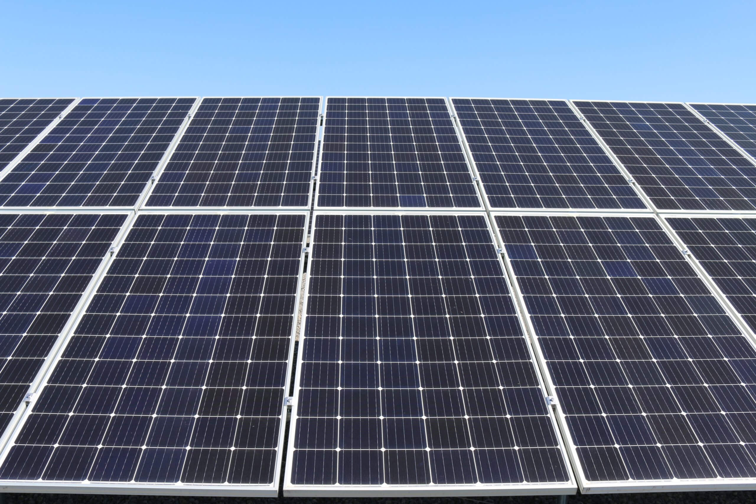
Monocrystalline silicon wafers are produced using the Czochralski process, where the crystal grows uniformly at 1420°C, forming a highly consistent atomic arrangement.
This physical trait gives the cells a uniform deep black or dark blue appearance, with surface reflectivity controlled below 2%.
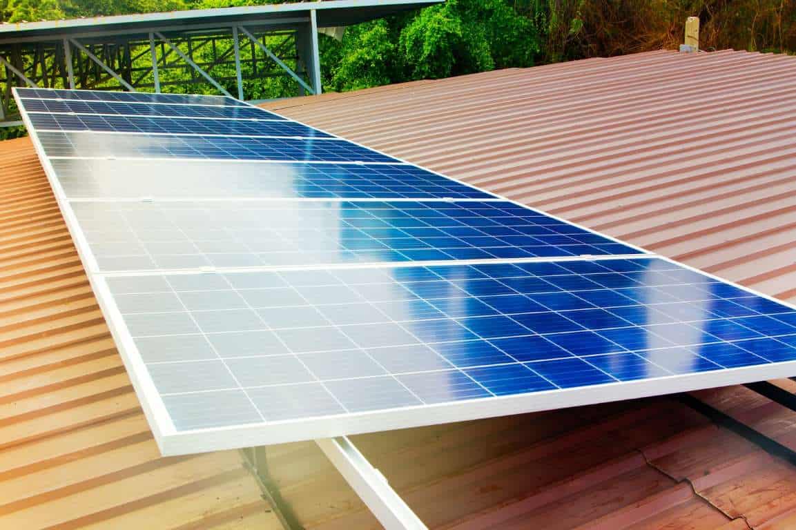
Polycrystalline silicon, containing many grains in different directions, presents a visible blue pattern or "cracked ice" look, with reflectivity as high as 5% to 10% and significant deviations in visual consistency.
The spacing between monocrystalline cells is reduced to 0.5–1.0 mm. Coupled with black backsheets and black anodized aluminum frames, the overall light absorption rate is improved by over 3%.
Surface reflectivity below 2%.
Visual color deviation ΔE less than 0.5.
Encapsulation transmittance as high as 94.5%.
Low-light absorption increased by 8%.
In high-end residential or Building Integrated Photovoltaics (BIPV) projects, the visual integration of these All-Black modules is 40% higher than ordinary modules.
Because the dislocation density inside monocrystalline silicon is below 500 per square centimeter, the cells do not require heavy metal busbars to assist in current collection.
Mainstream 9BB or 16BB technologies reduce the finger width to below 30 microns.
This micron-level metallization process not only reduces shading area by 2.5% but also makes the modules look like pure dark glass from 10 meters away.
Infrastructure Savings
Because the single-unit power of monocrystalline modules is generally 50 to 100 Watts higher than polycrystalline, building a power plant of the same capacity requires 15% to 18% fewer mounting rails.
In a 1 MW project, a monocrystalline system needs about 4500 fixing points, while a polycrystalline system needs over 5400.
During installation, the use of M8 bolts and mid-clamps is reduced by 900 sets, directly lowering hardware procurement costs by 0.05 RMB per Watt.
Simultaneously, the reduction in module count leads to the number of DC combiner boxes dropping from 12 to 10, and DC cable length is shortened by 1500 to 2000 meters accordingly.
Mounting & Cable System | Saving Ratio | Quantified Data (per 1MW) |
Mounting Rail Length | 16% Reduction | Saves 1.2 to 1.5 tons of aluminum |
DC Cable Loss | 0.8% Decrease | Reduces line loss by 8,000 W |
Installation Labor | 20% Shorter | Saves 30,000 to 50,000 RMB |
Foundation Pile Count | 12% Reduction | Saves 15 m³ of concrete |
In areas where land lease unit prices are 50 RMB per square meter per year, the 25-year rental cost can drop by 125,000 RMB per MW because monocrystalline systems save 25% of the land area.
Cable impedance loss is proportional to the square of the current.
The shorter cable distribution in monocrystalline systems improves the Performance Ratio (PR) by 1.5% to 2.0%.
This high degree of spatial intensification also shrinks the footprint of transformers and distribution cabinets by about 10%.
Higher Returns
The high efficiency of monocrystalline modules is not just about space savings; it represents an increase in return on investment per unit area.
Over a 25-year operational life cycle, the cumulative power generation per square meter of monocrystalline modules is about 5,500 kWh, while polycrystalline is only 4,200 kWh.
Calculated at 0.4 RMB per kWh, each square meter of monocrystalline area can create an additional 520 RMB in value.
Although the initial procurement price of monocrystalline is about 0.1 RMB/W higher, the Balance of System (BOS) cost is actually reduced by 0.15 to 0.25 RMB/W through savings in mounting, cables, labor, and land.
1,300 more kWh generated per m².
Land yield increased by 28%.
Investment payback period shortened by 1.2 years.
Levelized Cost of Energy (LCOE) dropped to 0.22 RMB.
When a factory roof can only install a 500 kW monocrystalline system or a 400 kW polycrystalline system, the annual net profit of the monocrystalline system is 45,000 RMB higher.
When calculating IRR, monocrystalline plants typically reach 8.5% to 11%, whereas polycrystalline plants often sit in the 6.5% to 7.5% range.
The surplus power from high-efficiency modules can meet over 95% of an enterprise's internal electricity needs, covering a load gap 15% larger than low-efficiency systems.
Improved Workability
The structural design of monocrystalline modules considers the convenience of installation personnel.
The weight of a single 550W module is maintained at about 28 kg, which is exactly within the safe load range for two workers.
The module frames undergo a 15-micron anodizing treatment, improving anti-slip performance by 10%. When installed on a roof with a 35-degree slope, their structural stability is higher.
MC4-compatible connector leads of 1.2 meters, combined with the compact arrangement of monocrystalline systems, reduce the plug-in time between adjacent modules from 45 seconds to 30 seconds.
Installation Process Metrics | Parameter Detail | Operational Benefit |
Connector Lead Length | 1,200 mm | Adapts to large-span mounting arrays |
Handling Frequency | 18 times/10 kW | 6 fewer carries than low-efficiency systems |
Fastener Torque | 16 N·m | Ensures wind pressure resistance of 2400 Pa |
Cleaning Interval | 120 to 180 days | Coating reduces dust adhesion by 35% |
During the later O&M stage, because there are fewer monocrystalline modules, the number of required annual infrared thermography inspection points is reduced by more than 20%.
Since the modules use high-transmittance self-cleaning glass with a surface contact angle greater than 110 degrees, the self-washing efficiency during rain is 45% higher than ordinary glass.
In water-scarce areas or regions with high labor costs, this saves 0.02 RMB/W in cleaning expenses annually.
The simplified design resulting from high efficiency reduces the total number of system failure nodes (connectors, convergence points) by 15% and increases the Mean Time Between Failures (MTBF) by approximately 5,000 hours.