What are the Poly Module Solar Technology In Cold Climates | 3 Challenges
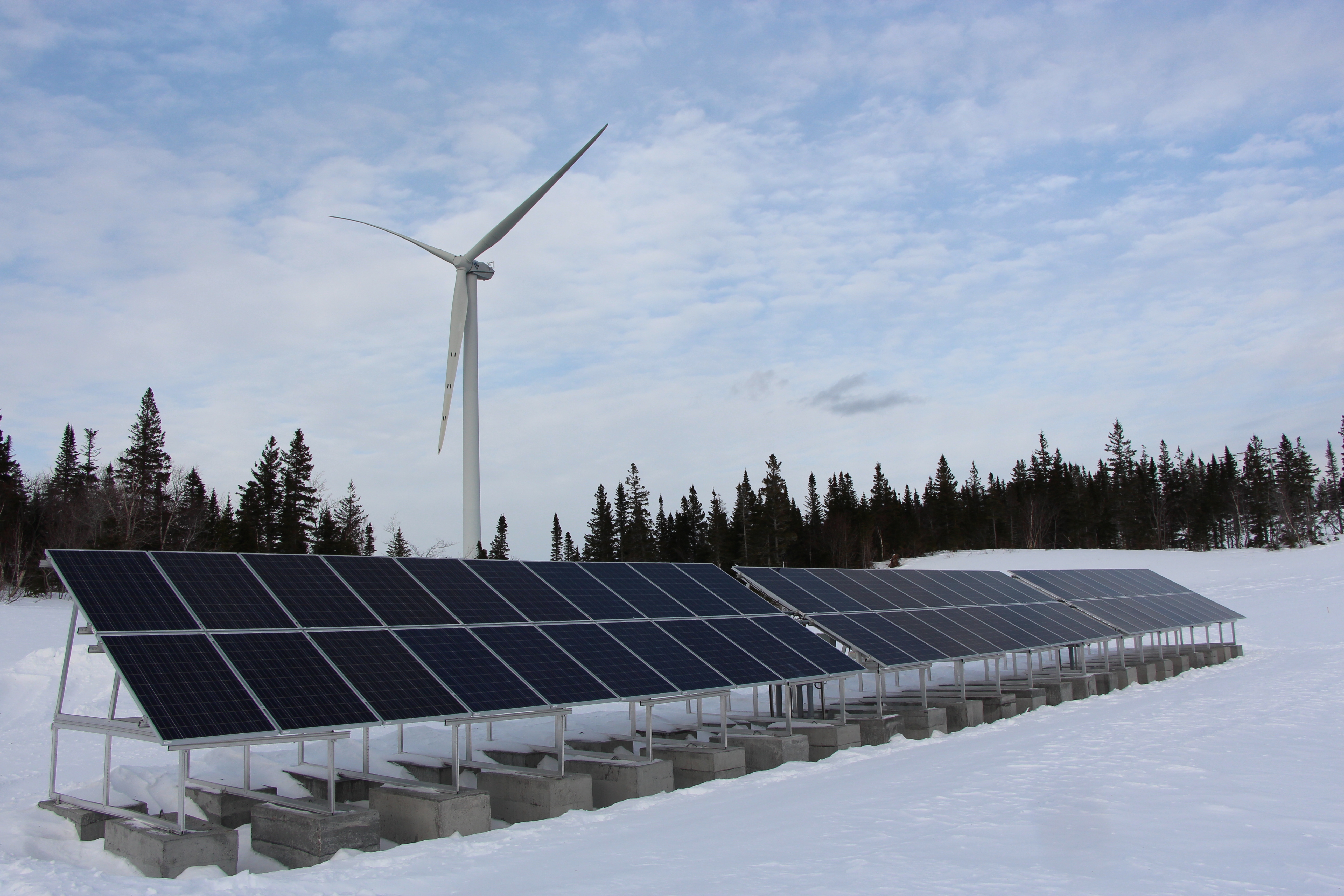
Polycrystalline modules face challenges in cold regions: 10 cm of snow accumulation can cause power generation to plummet by 90%;
Winter output is only 30% of summer output; extreme cold easily generates micro-cracks.
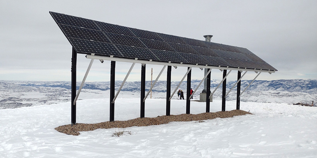
A tilt angle >45° is recommended to facilitate snow sliding, ensuring stable production and increased efficiency of the system.
Thermal Cycling & Micro-cracking
Hot and Cold Alternation
In extreme cycling tests from -40°C to 85°C, various materials inside polycrystalline silicon modules undergo intense physical expansion and contraction more than 200 to 500 times.
According to the IEC 61215 international standard, modules must maintain a power degradation rate of less than 5% under such temperature gradients.
However, in actual severe cold regions above 50°N latitude, annual temperature fluctuations cause micro-deformations of approximately 0.2% in the solder ribbons.
This thermal cycling effect repeats more than 9125 times over the 25-year lifecycle of a power station, directly inducing micro-cracks with a width of less than 50 microns in the solar cells.
This invisible mechanical damage slowly increases the series resistance of the module from an initial 0.3 ohms to over 0.8 ohms, leading to an additional decline of 2% to 3.5% in overall output power after 3 to 5 years of operation.
Material Conflict
The thermal expansion coefficient of polycrystalline silicon cells is only 2.6 ppm/°C, while the 3.2 mm tempered glass covering the surface is about 8.5 ppm/°C, and the busbar ribbons (usually tin-coated copper) connecting the cells reach as high as 17 ppm/°C.
In a 40°C temperature drop—from 10°C at noon to -30°C in the early morning—the expansion coefficients of the three materials differ by 3 to 6 times, generating shear stresses as high as 15 to 25 MPa inside the encapsulation layer.
This stress concentrates at the 0.5 mm wide solder joints, causing more than 10% plastic strain in the solder layer and increasing the probability of cross-shaped or dendritic micro-cracks at the cell edges.
The table below lists the physical mismatch parameters of different encapsulation materials in extreme cold environments:
Material Name | Thermal Expansion Coefficient (ppm/°C) | Displacement Difference at 40°C Temp Difference (μm) | Contribution Rate to Micro-cracks (%) |
Polycrystalline Wafer | 2.6 | 1.04 | 5% |
Tempered Glass | 8.5 | 3.40 | 25% |
Tin-coated Copper Ribbon | 17.0 | 6.80 | 55% |
EVA Film | 200.0 | 80.00 | 15% |
Efficiency Drop
After micro-cracking occurs, the effective conductive area of the cell decreases by about 10% to 15%.
Through EL (Electroluminescence) testing, it is found that when the micro-crack area exceeds 8% of a single cell's area, the current transmission efficiency in that region loses more than 30%.
In actual power generation, this causes the Fill Factor (FF) of polycrystalline modules to drop from a standard 78% to below 72%.
When the ambient current density reaches 9 A, the broken grid lines generate more than 5 W of additional heat within a local area of 2 square centimeters, forming hot spots with temperatures exceeding 65°C, which is about 25°C higher than normally operating cells.
This localized high temperature further accelerates the yellowing of the EVA film within 15 years, reducing light transmittance by 3% to 5% and creating a vicious cycle of performance degradation.
Where It Breaks
Statistical analysis of 1000 polycrystalline modules operating in high-cold regions for 10 years revealed that 65% of micro-cracks occur in the 24 cells near the junction box. Due to uneven heat dissipation from the backsheet, thermal stress fluctuations here are 12% higher than at the edges.
About 45% of the cracks are penetrating cracks parallel to the solder ribbons; these lead to an instantaneous 15% to 20% drop in a single cell's power output.
Another 30% are edge cracks between 5 and 10 mm in length. Although they cause only a 0.5% power fluctuation in the short term, under wind loads of 2400 Pa, these micro-cracks can extend by 50% in length within 48 hours, eventually evolving into irreversible circuit failures.
Choose Thicker Ones
To reduce losses from thermal cycling, choosing polycrystalline modules with 2.5mm dual-glass encapsulation can reduce deformation under mechanical loads by more than 15%.
Using POE (Polyolefin Elastomer) instead of traditional EVA as the encapsulation film provides a water vapor transmission rate of only 0.5g/m²·day—far lower than EVA's 20g/m²·day—effectively preventing snowmelt from seeping in through micro-cracks and causing a >10% leakage risk in diodes.
Reducing ribbon thickness from 0.2 mm to 0.15 mm and adopting multi-busbar (12 BB or more) designs can shorten the current transmission path by about 25%.
Even if a 20-micron micro-crack occurs locally, the current can still bypass the break through other grid lines, thereby controlling the power loss of the entire module in extreme cold to within 0.3% and ensuring an 8% to 12% increase in cumulative 20-year returns.
Loose Bolts
In seasonal temperature fluctuations of 40°C, the different contraction rates of the aluminum alloy frame and the steel bracket cause the tightening torque of M8 bolts to drop from an initial 20 N·m to 16 N·m, a 20% decay rate.
This looseness causes the module to produce low-frequency vibrations of 5 to 10 Hz when wind speeds exceed 15 m/s, which in turn generates alternating stresses of 2 MPa per second inside the cells.
The probability of micro-cracking in such a vibrating environment is 35% higher than in a stable state.
It is recommended to conduct torque spot checks every 24 months to keep the bolt looseness rate below 2%, ensuring the structural integrity and a service life of over 25 years for the 50 kW system.
Mechanical Snow Loading
Snow is Too Heavy
A standard 72-cell polycrystalline module measuring 2,279mm x 1,134mm has a light-receiving area of approximately 2.58 square meters.
When the snow depth reaches 30 cm, if it is dry snow (density approx. 100 kg/m³), the module surface must withstand a static load of 77.4 kg.
Once it turns to wet snow (density can reach 400 kg/m³ to 600kg/m³), the weight of the same snow thickness can soar to over 309 kg, equivalent to the weight of 4 adult men pressing on less than 3 square meters of glass.
According to IEC 61,215 standards, the front static load test value for ordinary modules is 5400 Pa, roughly 550 kg per square meter. This means, when encountering extreme wet snow accumulation of over 80 cm, the module is already approaching its physical design limit, and the probability of permanent deformation increases by 45%.
In regions north of 40°N, continuous snowfall for 72 hours can lead to snow accumulation at the bottom of the array exceeding 1.5 m.
This bottom snow creates an upward lifting force and lateral pressure on the bracket; lateral pressure peaks can reach 20 N per square decimeter under a 15°C temperature difference.
If the installation height is lower than 1.2 times the local historical maximum snow depth, the bottom modules will be buried in snow, causing the stress concentration at the frame-to-bracket connection to increase by 3 times.
At -25°C, although the yield strength of the aluminum alloy frame improves slightly, its brittleness increases by 12%, raising the probability of a >1 mm gap appearing at the frame corner connections to 18% under uneven loads.
Frame Bending
Polycrystalline modules typically use 3.2mm or 4mm thick tempered glass paired with aluminum alloy frames 35mm to 40mm in height.
When subjected to a simulated load of 2400 Pa, the center deflection (bending displacement) of the glass is usually between 10 mm and 15 mm.
When the load increases to 5400 Pa, the displacement at the center of large-format modules may exceed 25 mm. This severe geometric deformation subjects the 180-micron thick internal polycrystalline silicon wafers to enormous tensile stress.
Experimental data shows that when the deflection exceeds 1.5% of the module's short-side length, the risk of micro-cracks at the cell edges jumps from a normal 0.5% to approximately 22.8%.
To resist this physical compression, increasing the frame wall thickness is an effective measure.
Increasing the wall thickness of 6063-T5 aluminum from 1.1 mm to 1.5 mm can improve the longitudinal bending strength of the module by more than 25%. The table below compares the physical performance of modules with different specifications under the same snow load:
Frame Height (mm) | Glass Thickness (mm) | Displacement at 5400 Pa (mm) | Structural Failure Probability (%) | Cost Increase Ratio (%) |
30 | 3.2 | 32.5 | 35 | 0 |
35 | 3.2 | 22.1 | 12 | 5.5 |
40 | 3.2 | 16.8 | 4 | 11.2 |
35 (Dual-Glass) | 2.5+2.5 | 14.2 | 2 | 18.5 |
Cell Cracking
Micro-cracks caused by snow loads usually appear in radial or cross patterns, manifesting as distinct dark areas under EL (Electroluminescence) testing.
When snow is unevenly distributed (e.g., thicker snow on the lower half of the module), the local stress difference inside the cell can reach 15 MPa.
Under this asymmetric pressure, grain boundary weaknesses within the polycrystalline silicon wafer evolve into penetrating cracks longer than 5 cm, causing an 8% to 15% loss in output current for that cell string.
If a crack cuts through more than three main busbars, the power output of that cell will drop by 40% directly, triggering the bypass diode and causing the entire module's voltage to decrease by about 12V.
Over an actual 20-year operating cycle, after experiencing more than 200 instances of heavy snow cover, the cumulative micro-crack rate for unreinforced modules typically reaches 15% to 30%.
These microscopic injuries evolve into hot spot effects in high-temperature summer environments; local temperatures can rapidly rise to over 85°C under 1,000 W/m² sunlight, which is 35°C higher than surrounding normal cells.
Encapsulant carbonization caused by hot spots increases the annual degradation rate from a nominal 0.7% to 1.5% or even higher.
By adopting Multi-Busbar (MBB) technology—increasing the number of busbars to 12 or more—the risk of power loss after a single severe snow load can be reduced by 60%, as the dense electrode network provides more escape paths for the current.
Sliding Off
At a 30° installation angle, the static friction coefficient between snow and the glass surface is between 0.2 and 0.5. Snow often needs to accumulate to over 20 cm before it slides off due to gravity.
If the tilt angle is increased to 50°, the probability of snow remaining decreases by 45%. Even at -10°C, snow thicker than 5 cm has an 80% probability of sliding off naturally within 4 hours.
This self-cleaning effect contributes about 3.5% to 6% to the 25-year power station revenue, as it not only reduces mechanical pressure but also effectively increases power generation time.
When designing brackets, the height of the module bottom from the ground must have a redundancy of at least 80 cm.
This is because sliding snow accumulates in front of the array. If the bottom clearance is insufficient, the piled snow will push back against the module's bottom edge, generating a thrust of over 500 N per linear meter.
This thrust can cause a distortion of more than 2 mm in the bottom frame, tearing the silicone sealant layer and increasing the probability of snowmelt water seeping into the module by 25%.
Using Anti-Reflective (AR) coating glass with high snow-sliding properties can reduce the critical angle for snow sliding by about 5°, maintaining a lower mechanical load even in cold regions at lower latitudes.
Holding Firm
To ensure the system is not crushed by snow loads over 25 years, the purlin spacing of the bracket must be strictly controlled at about 60% of the module's long side.
For a module 2.2 m long, the ideal support points should be 400 mm to 500 mm from the edges.
Using C-channel steel brackets with reinforcement ribs, the cross-sectional thickness should be no less than 2.5 mm, and the galvanized layer thickness must reach 85 microns or more to prevent corrosion from snowmelt. Although this configuration increases initial bracket costs by 15%, it reduces the risk of structural collapse to below 0.01%.
In the O&M budget, an annual snow removal fee of 20 to 50 USD/kW should be reserved, but this is only for extreme blizzard conditions.
Excessive manual snow removal with improper tools (such as hard shovels) can cause scratches deeper than 0.1 mm on the glass surface, reducing the glass's mechanical strength by 20% and leading to a 1.5% loss in light transmittance.
From an ROI perspective, in regions where snowfall exceeds 100 mm/year, the 8% extra initial cost invested in increasing module mechanical load ratings and optimizing installation angles can usually be fully recovered by the 6th to 8th year of operation through reduced maintenance costs and increased winter power generation.
Low Irradiance Performance
The Light Has Weakened
In the winter of cold regions, solar radiation intensity typically drops from 1000 W/m² under Standard Test Conditions (STC) to between 150 W/m² and 400 W/m².
For a polycrystalline silicon module rated at 330 W, its short-circuit current (Isc) decreases almost linearly with irradiance, but the drop in open-circuit voltage (Voc) follows a logarithmic rule.
When irradiance drops to 200 W/m², the Voc decrease is typically only 5% to 8%, while Isc will drop by about 80% simultaneously.
This means modules can still maintain a high voltage output in weak light, sufficient to trigger the inverter's startup threshold of 150V to 200V.
However, the conversion efficiency of polycrystalline silicon cells is not constant under low radiation; limited by the increase in internal carrier recombination rates, their relative efficiency at 200 W/m² will show a systematic decline of 3% to 6% compared to 1000 W/m².
Due to the low-temperature effect brought by cold climates, the Fermi level inside the cell shifts, which to some extent compensates for the voltage loss caused by weak light.
Experimental data shows that in an environment of -10°C with an irradiance of 200 W/m², the actual output voltage of a polycrystalline module might be about 2 V higher than under 25°C standard conditions.
This "low-temperature voltage gain" allows the system to maintain longer online operation times even on cloudy winter days, contributing an extra 15 to 20 minutes of effective working time daily compared to warm regions.
The following are typical electrical performance parameter changes for polycrystalline modules under different irradiance levels:
Irradiance (W/m²) | Relative Efficiency (%) | Output Current (A) | Output Voltage (V) | Power Output (W) |
1000 | 100.0 | 9.25 | 34.2 | 316.3 |
800 | 99.4 | 7.41 | 33.9 | 251.2 |
600 | 98.2 | 5.54 | 33.5 | 185.6 |
400 | 96.5 | 3.68 | 32.8 | 120.7 |
200 | 94.1 | 1.84 | 31.5 | 58.0 |
Current Cannot Flow
Shunt resistance (Rsh) is the decisive physical parameter for the low-light performance of polycrystalline silicon modules.
During the production of polycrystalline wafers, the presence of grain boundaries can form parasitic parallel branches. If the shunt resistance is below 2000 Ω·cm², more than 10% of the trace current generated in weak light will be lost through these parasitic branches and cannot enter the external load.
High-quality polycrystalline modules optimize the diffusion process to increase shunt resistance to over 5000 Ω·cm², ensuring that the Fill Factor (FF) remains above 0.70 even under extreme weak light of 100 W/m².
Meanwhile, the influence of series resistance (Rs) weakens significantly in low light.
Since the power loss caused by Rs is proportional to the square of the current, when the current drops from 9A to 1.8A, the internal resistance heat loss is reduced by 25 times, which physically mitigates part of the efficiency drop.
In actual system design, the low current under weak light changes the proportion of voltage drop losses in combiner boxes and DC cables.
At a full load of 1,000 W/m², cable voltage drop might account for 1.5% of system losses, but at a weak light of 200 W/m², because the current is so small, the cable voltage drop loss shrinks to below 0.1%.
Taking advantage of this, in cold, low-radiation areas, the string length can be appropriately increased to push the DC side voltage into the inverter's highest MPPT efficiency range (usually 600V-800V), thereby compensating for the 3% weak-light efficiency loss of the cells themselves.
Spectrum Has Changed
As the solar elevation angle decreases, the Air Mass (AM) usually increases from standard AM 1.5 to AM 2.5 or higher.
This means the path of sunlight through the atmosphere lengthens, and Rayleigh scattering causes the blue light module (400 nm-500 nm) in total radiation to increase by 10% to 15%.
Polycrystalline silicon cells have a quantum efficiency (QE) of about 90% for long-wave light from 600 nm to 950 nm, but their short-wave response near 400 nm is slightly inferior to monocrystalline PERC cells.
This spectral mismatch leads to a spectral gain for polycrystalline modules in winter cloudy weather that is about 1.5% lower than in summer.
To offset this spectral disadvantage, using glass with a high-transmittance Anti-Reflective (AR) Coating is crucial.
The average transmittance of such glass should reach over 94% across the full 400nm to 1100nm band.
According to measurements, polycrystalline modules with special anti-reflective coatings produce 2.2% more current output at 200 W/m² than modules with ordinary glass.
Furthermore, because the surface texture (fluff) of polycrystalline silicon wafers is relatively irregular, its absorption capacity for diffuse horizontal irradiance (DHI) at certain incident angles is even 0.8% higher than that of flat monocrystalline structures, making its cumulative annual power generation (kWh) more resilient in cold regions with heavy cloud cover.
Calculate the Costs Clearly
The final indicators for evaluating weak-light performance are the specific energy yield (kWh/kWp) and the Levelized Cost of Electricity (LCOE).
During the 120 days of low-irradiance winter, the power generation per kilowatt of polycrystalline modules is approximately 40 to 55 kWh.
Although the power generation of monocrystalline modules under the same conditions might be 5% to 7% higher, polycrystalline modules currently have a cost advantage of 12% to 18% in the procurement phase.
For a 5 MW ground power station, adopting polycrystalline technology can save approximately 250,000 to 400,000 USD in initial investment.
Calculating the 25-year lifecycle returns, the ROI of polycrystalline systems in cold, low-light regions can often be maintained between 10% and 12%.
The DC/AC Ratio in system design is the financial lever for optimizing weak-light returns.
In cold regions with insufficient sunlight, it is reasonable to increase the oversizing ratio to 1.4 or even 1.6.
While this leads to about 2% curtailment loss during summer mid-days, it allows the inverter to work in full-load or high-efficiency zones for 80% of its winter operating time, increasing the system's annual equivalent utilization hours by 100 to 150 hours.
The table below summarizes the economic comparison under different installation strategies:
Parameter Item | Standard Configuration (1.2 Oversizing) | Low-Light Optimized Configuration (1.5 Oversizing) | Difference |
Initial Investment (USD/W) | 0.85 | 0.98 | +15.3% |
Winter Monthly Power Generation (kWh) | 4500 | 6100 | +35.5% |
Summer curtailment loss (%) | 0.5 | 3.2 | +2.7% |
25-Year Total Revenue (USD) | 1,200,000 | 1,450,000 | +20.8% |
Payback Period (Years) | 7.2 | 6.5 | -9.7% |
How to Configure Inverters
The Maximum Power Point Tracking (MPPT) accuracy of an inverter usually deteriorates at low input power, dropping from 99.9% to around 98.5%.
Priority should be given to equipment with multiple MPPTs and a startup power lower than 0.5% of the nominal power.
If a 100 kW inverter has a startup power of 500 W, it means that in early morning or extremely overcast conditions, when the total string power is below this value, the system will not generate power at all, causing a 1% unnecessary loss in annual power generation.
At the same time, the static power consumption of the inverter needs to be strictly controlled.
In an environment of -20°C, the heating elements and control circuits inside the inverter will consume 20 W to 50 W of standby power.
If the string output under weak light is only 100 W, the effective electrical energy sent to the grid will be significantly reduced after subtracting standby power.
Adopting string inverters with intelligent sleep modes and low-loss modules, combined with high-voltage DC side designs, can improve the system efficiency (PR value) of power stations in cold regions by 2% to 4%, ensuring that even in difficult moments with only 100 W of sunlight per square meter, every charge can be effectively converted into cash revenue.