What is the most expensive part of solar panels?
The most expensive part of a solar panel is the solar cells, accounting for approximately 60% of the cost.
The processing of high-purity silicon, the core material, is extremely complex. It is recommended to pay attention to conversion efficiency, as it directly determines long-term power generation returns.
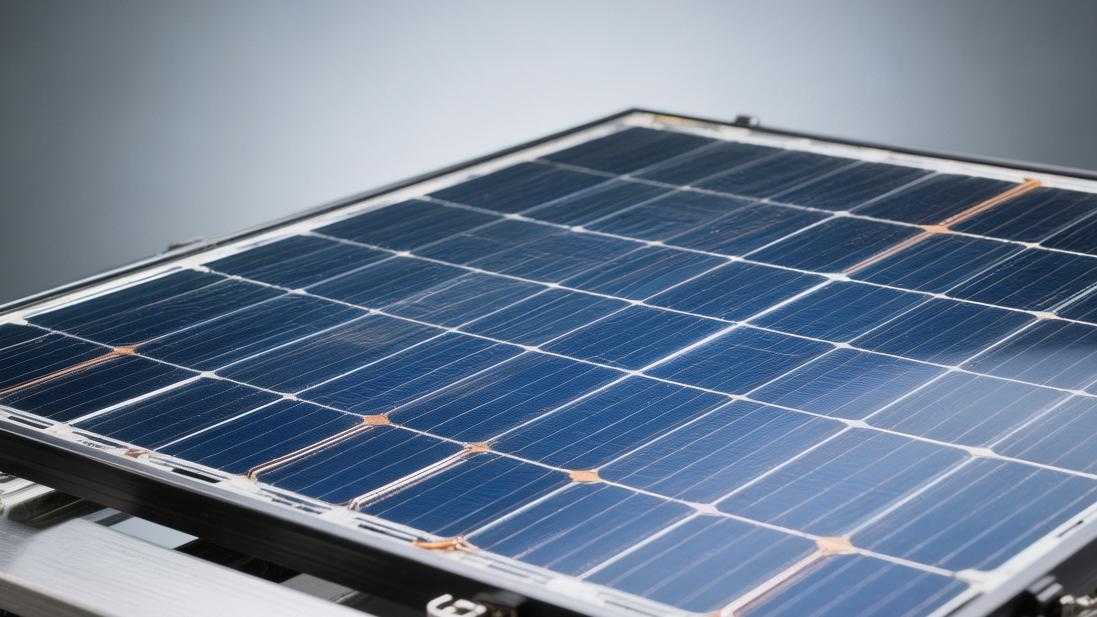
The Core Module
High Silicon Material Cost
Normally, producing 1 GW (Gigawatt) of solar cells consumes approximately 2,300 to 2,600 tons of silicon material.
The purity requirements for these silicon materials are extremely high, with solar-grade standards usually reaching 99.9999% or even 99.9999999%.
When the price of silicon material is in the range of 80,000 RMB per ton, the silicon cost per watt of the solar cell is approximately between 0.18 and 0.21 RMB.
If the price of silicon material rises to 200,000 RMB per ton, the cost per watt will immediately follow and rise to above 0.5 RMB.
In the total selling price of a solar panel (approximately 1.0 RMB/W), the expenditure ratio of this raw material often fluctuates within the range of 30% to 45%.
· The pulling process of monocrystalline silicon ingots must be conducted in high-temperature furnaces above 1400 degrees Celsius.
· A monocrystalline silicon ingot with a length of approximately 4 meters and a diameter of 8 inches usually has a growth cycle between 48 and 72 hours.
· In the silicon material currently required for N-type cells, the oxygen content must be controlled below 10 ppma (parts per trillion) to reduce later power generation loss.
· In the cost structure, electricity consumption accounts for 35% of silicon material production expenses, with an average of 50 to 60 kWh of electricity consumed for every 1 kg of silicon produced.
Thickness Matters
Current mainstream M10 specifications (182mm x 182mm) and G12 specifications (210mm x 210mm) silicon wafers have seen their thickness reduced from the early 180µm (micrometers) to between 130µm and 150µm.
For every 10 µm reduction in thickness, the silicon cost per watt can be reduced by approximately 3% to 4%.
The diameter of the diamond wire used for cutting has narrowed down to 35µm to 40µm, which helps reduce cutting loss (increasing the yield rate).
During the cutting process of a silicon ingot, approximately 25% of the silicon material is lost as silicon powder.
· The light-receiving area of an M10 wafer is approximately 33,124 square millimeters, while the G12 wafer reaches 44,100 square millimeters.
· Using 35µm diamond wire for cutting, the yield per kilogram of silicon material can reach 65 to 70 pieces (calculated based on 182 mm specifications).
· Thinning reduces the material cost by 0.02 RMB/W, but it also increases the breakage rate by about 1.5%, requiring higher-precision automated robotic arms for handling.
· The resistivity of silicon wafers is usually controlled between 0.5 Ω·cm and 1.5 Ω·cm, which determines the speed of charge flow within.
Efficiency Decides the Outcome
The average mass production efficiency of current mainstream TOPCon (Tunnel Oxide Passivated Contact) cells is between 24.8% and 25.5%.
Compared to the older PERC technology (average efficiency 23.2%), for every 1% increase in efficiency, the total power generation over a 25-year life cycle increases by 4% to 6% for the same installation area.
This efficiency improvement can reduce the system balance of system (BOS) cost by about 0.05 RMB per watt, as costs for brackets, cables, and land leasing are diluted by more electricity generation.
· In laboratory environments, the theoretical maximum efficiency of single-junction crystalline silicon cells (Shockley-Queisser limit) is approximately 29.4%.
· The mass production efficiency of HJT (Heterojunction) cells is currently distributed between 25.5% and 26.2%, but the initial investment for its production equipment is more than 50% higher than that of TOPCon.
· The open-circuit voltage (Voc) of TOPCon cells is usually between 710 mV and 730 mV, which is about 30 mV higher than that of PERC cells.
· Bifaciality refers to the ratio of the back-side power generation capability to the front-side. Currently, the bifaciality of mainstream products has reached 80% to 85%.
Pay Attention to Degradation
Due to the effects of Light-Induced Degradation (LID) and Light-and-Elevated-Temperature-Induced Degradation (LeTID), the first-year degradation is usually between 1% and 1.5%.
Over the subsequent 24 years, the annual power decline rate needs to be controlled within 0.4% to 0.55%.
If the degradation rate of a 550W module is too high, the remaining power after 25 years may only be 80% of the rated value or even lower, significantly extending the investment payback period.
Because N-type silicon wafers do not contain boron-oxygen pairs internally, their anti-degradation ability is stronger than P-type wafers, allowing the system to generate about 2% more long-term returns.
· The 25-year power warranty for high-quality modules is usually between 87% and 89% of the initial value.
· Potential Induced Degradation (PID) can cause a sudden power drop of more than 30% in high-temperature and high-humidity environments, which needs to be controlled through the resistivity of the encapsulant film.
· For every 1 degree Celsius increase in the operating temperature of the module, its output power will drop by 0.3% to 0.35% (power temperature coefficient).
· If the hot spot temperature exceeds 150 degrees Celsius, it may cause permanent physical damage to the local solar cell, reducing its lifespan by more than 10 years.
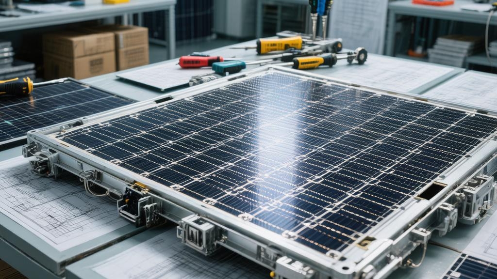
Precision in Production
TOPCon cells usually require 12 to 14 steps, including surface texturing, diffusion, LPCVD (Chemical Vapor Deposition) growth, etching, printing, and sintering.
The yield (pass rate) of each step must be maintained above 98%.
If the total yield drops from 98% to 95%, the average production cost per watt will increase by approximately 0.03 RMB.
In addition, the cleanliness of the production environment needs to reach Class 10,000 or even Class 1,000 standards to prevent tiny dust particles from causing short circuits.
· The single loading capacity of an LPCVD furnace tube is usually between 400 and 600 pieces, with a reaction time of about 2 hours.
· The pulse frequency of laser grooving technology reaches the megahertz level, and the positioning accuracy must be controlled within ±5µm.
· The speed of automatic screen printing machines has reached 4,000 to 6,000 pieces per hour, and the pressure deviation cannot exceed 1 Newton.
· The temperature control accuracy of the sintering furnace is required to be within ±1 degree Celsius to ensure good ohmic contact between the silver paste and the silicon wafer.
The "Secret" Ingredient
Plastics are Not Simple
Between the outer frame of the solar module and the internal silicon wafers, there is a layer of polymer film with a thickness usually between 0.4 mm and 0.6 mm.
This material is commonly known as encapsulant film. Although it accounts for only 5% to 8% of the total module cost, it bears 80% of the responsibility for ensuring the module's 25 to 30-year lifespan.
Currently, mainstream materials are divided into two types: EVA (Ethylene-Vinyl Acetate copolymer) and POE (Polyolefin Elastomer).
The Vinyl Acetate (VA) content of EVA film usually needs to be maintained between 28% and 33% to ensure that it can produce sufficient cross-linking reactions when heated to 140 to 150 degrees Celsius.
After the cross-linking degree reaches more than 85%, the film will transform from a solid state to an elastomer, firmly bonding the cells, glass, and backsheet together.
The peel strength of the film needs to be greater than 60 N/cm to prevent delamination in extreme temperature difference environments (-40 degrees Celsius to 85 degrees Celsius).
Each square meter of solar module requires about 1.1 to 1.2 square meters of film, with a gram weight usually between 400 and 550 grams.
Real Waterproofing Capabilities
Since N-type cells (such as TOPCon or HJT) are extremely sensitive to moisture, traditional EVA film will decompose under long-term light and damp-heat conditions, producing acetic acid, which in turn corrodes the silver grid lines of the cells.
The Water Vapor Transmission Rate (WVTR) of EVA is usually between 20 and 40 g/m²·24h, while high-performance POE film can reduce this value to below 5 g/m²·24h, a reduction of more than 75%.
In the design of double-glass modules, using one layer of POE combined with one layer of EVA in an "EPE" structure (extrusion composite film) has become a choice to balance cost and performance.
This structure allows the module to maintain a power degradation of within 2% after 3000 hours in the Double 85 test (85 degrees Celsius temperature, 85% humidity).
· The price of POE film is usually 30% to 50% higher than that of ordinary EVA, with a price difference of about 3 to 5 RMB per square meter.
· In high-humidity floating solar projects, 100% pure POE encapsulation is a mandatory configuration.
· If the accumulation of acetic acid content exceeds 100 ppm, it will trigger significant blackening of grid lines and an increase in resistance.
· The refractive index of the film needs to be controlled between 1.48 and 1.50 to best match the interface of the glass and silicon wafers.
Transparency for Power Generation
High-quality film must have a light transmittance of over 91.5% in the wavelength range of 380 nm to 1100 nm.
To increase power generation, the industry has developed "high-transparency" films specifically optimized for the ultraviolet region of 300 nm to 380 nm.
Ordinary films add UV absorbers to protect the backsheet from UV damage, with a cutoff wavelength usually at 360 nm.
However, if UV-permeable film is used instead, the output power per watt can be increased by about 0.5% to 1%, which means an additional 3W to 5W of rated power for a 550W module. Over a 25-year operation period, this gain can generate about 150 kWh of additional electricity income.
For every 10% increase in UV transmittance, the short-circuit current (Isc) of the cell increases by about 0.1 Amperes.
In long-term outdoor operation, the yellowness index (YI) growth of the film cannot exceed 3; otherwise, it will lead to serious power loss.
Pressure Resistance for Lifespan
Potential Induced Degradation (PID) is an invisible loss in solar systems, occurring mainly in high-voltage environments (usually 1000V or 1500V) between the cells and the grounded frame.
The volume resistivity of the film is the main weapon against PID.
The resistivity of EVA film is usually 10 to the 14th power Ohm·cm, while POE film can reach 10 to the 15th or even 10 to the 16th power Ohm·cm.
Higher resistivity means the resistance to charge flow has increased by more than 10 times, effectively preventing sodium ions (from the glass) from migrating to the cells.
In 1500 V high-voltage systems, using high-impedance film can reduce leakage current loss by more than 90% after 10 years of operation.
· The PID phenomenon may cause the first-year power generation of power stations in high-temperature and high-humidity areas to plummet by more than 25%.
· The insulation resistance of the module must be greater than 40 MΩ·m² in the wet leakage current test.
· The elongation at break of the film should be maintained above 400% to buffer the mechanical stress caused by hail impact or snow pressure.
· During the encapsulation process, the vacuum level of the laminator needs to reach below 100 Pascals (Pa) to completely eliminate air bubbles.
Calculating the Details of Thickness
In actual production, the thickness control of the film is extremely precise, with tolerances usually kept within ±2%.
If you reduce the thickness from 0.50 mm to 0.45 mm, the material expenditure per module can be reduced by about 10%. However, when encountering uneven cell surfaces or thick solder ribbons, thinning will cause the lamination bubble rate to rise from 0.1% to over 1.5%.
Currently, large-size modules (such as 2,384 mm x 1,134 mm) have extremely high requirements for the dimensional stability of the film, with heat shrinkage required to be less than 1.5%.
If shrinkage goes out of control, it will cause the cells to shift inside the laminator, resulting in uneven spacing or even micro-cracks. This fluctuation in the defect rate will directly increase the cost per watt by about 0.02 RMB in disguise.
The white EVA film used on the back of single-glass modules needs to have a reflectance of over 70% to utilize gap light and increase power generation gain by about 1%.
The density of POE is about 0.88 g/cm³, slightly lower than the 0.95 g/cm³ of EVA, meaning POE is lighter for the same thickness.
Structural Parts
The frame is vital
In the non-cell cost of solar modules, the expenditure on aluminum alloy frames usually accounts for 13% to 15%.
This frame mainly uses architectural aluminum of 6063-T5 or similar grades, which possesses good mechanical strength and corrosion resistance.
For a 72-cell module with an area of about 2.58 square meters, the weight of the aluminum frame is usually between 2.8 kg and 3.5 kg.
The wall thickness design of the frame is very precise. Mainstream products have longitudinal and transverse wall thicknesses ranging from 1.3 mm to 1.8 mm.
This structure allows the entire panel to withstand 5400 Pascals (Pa) of positive snow load pressure and 2400 Pascals of back-side wind load pressure.
To prevent oxidation during 25 years of outdoor operation, the surface of the aluminum frame must undergo anodizing treatment, with the oxide film thickness usually required to be 12 micrometers (µm) to 15 micrometers or more.
If the film thickness is below 10 micrometers, modules operating for about 5 years in coastal areas with severe salt spray will show obvious white spots or pitting on the edges, leading to a reduction in mechanical load capacity by more than 20%.
In addition, the cavity design of the frame must consider not only strength but also reserve 4 to 8 installation holes with a diameter of about 9 mm, and 2 to 4 grounding holes for electrostatic grounding to ensure the electrical safety of system operation.
Performance Dimension | Quantitative Indicators and Parameters |
Tensile Strength | The tensile strength of 6063-T5 aluminum should not be less than 160 megapascals (MPa). |
Yield Strength | Yield strength is usually maintained above 110 megapascals, ensuring no permanent deformation after pressure. |
Weight Proportion | The weight of the frame accounts for 12% to 14% of the total weight of a module, which is about 25 kg. |
Cost Fluctuation | For every 1000 RMB/ton increase in aluminum ingot prices, the cost per watt of the module rises by about 0.008 RMB to 0.012 RMB. |
Transparent Armor
The tempered glass covering the top layer of the solar cells is a physical barrier protecting the precision internal structures. Its weight often accounts for 65% to 70% of the entire module's total weight.
Currently, mainstream single-glass modules use 3.2mm thick ultra-white embossed tempered glass, while double-glass modules use a layer of 2.0mm thick semi-tempered or fully tempered glass on both the front and back.
The iron content of this glass must be controlled below 150 ppm (parts per million) to ensure extremely high light transmittance.
By coating the glass surface with an anti-reflection (AR) film about 120 nanometers thick, the light transmittance can be increased from 91% to over 93.8%, which means an additional 20 watts of light energy can be captured per square meter.
The physical performance requirements for tempered glass are very strict. In impact tests, it must withstand the impact of a hailstone with a diameter of 25 mm and a mass of 7.53 grams at a speed of 23 meters per second without breaking.
The flatness error of the glass must be controlled within 0.2%; otherwise, uneven force during the lamination process will lead to micro-cracks in the internal cells. These cracks are invisible to the naked eye but appear as distinct black lines under infrared testing, causing an immediate 10% or more drop in power in that area.
Performance Dimension | Quantitative Indicators and Parameters |
Glass Density | The density of standard photovoltaic glass is approximately 2.5 g/cm³. |
Bending Strength | After tempering, the bending strength of the glass can be increased from 30 MPa to over 120 MPa. |
Transmittance Gain | AR coating can increase the short-circuit current (Isc) of the module by 2.5% to 3%. |
Thermal Expansion Coefficient | The linear expansion coefficient is approximately 9 x 10⁻⁶/℃, which needs to match the thermal expansion and contraction rates of the aluminum frame and the film. |
Current Outlet
The junction box is the hub for the module's power output. Although its cost only accounts for 2% to 3% of the total price, it is the module with the highest failure rate and the greatest impact on safety.
A qualified junction box must reach the highest protection rating of IP68, ensuring that no short circuit occurs under heavy rain or short-term water immersion.
Internally, it usually integrates 3 bypass diodes with a rated current usually between 20 Amperes and 30 Amperes to match the high current generated by current 182 mm or 210 mm large-size cells.
When hot spot effects occur due to shading of the cells, the bypass diode will automatically turn on, allowing the current to bypass the obstructed area and preventing the local temperature from soaring above 150 degrees Celsius and burning the backsheet.
The internal contact resistance of a high-quality junction box should be controlled below 1 milliohm (mΩ) to reduce unnecessary power loss.
Cables connecting the junction box usually use 4 square millimeter solar-specific wires, with lengths ranging from 1.1 meters to 1.4 meters, capable of withstanding 1500 volts (V) of high voltage.
These wires need to pass TUV or UL certification, possessing up to 25 years of anti-UV and anti-aging capabilities, ensuring that the loss rate during current transmission is below 0.5%.
Performance Dimension | Quantitative Indicators and Parameters |
Diode Voltage Drop | The conduction voltage drop is usually between 0.4 Volts and 0.6 Volts. The lower the voltage drop, the less heat generated. |
Maximum Rated Voltage | The system-side voltage rating must reach 1500 Volts (DC), and the leakage current should be less than 5 microamperes. |
Cable Temperature Resistance | Wires need to maintain flexibility and insulation at ambient temperatures from -40 degrees Celsius to 120 degrees Celsius. |
Flame Retardant Rating | The plastic shell of the junction box must meet the highest flame retardant standard of UL94-V0. |
Thin Back Barrier
Current mainstream backsheets use a three-layer composite structure, such as the classic TPT (Polyvinyl Fluoride/Polyester/Polyvinyl Fluoride) or the more cost-effective KPE.
The middle polyester layer (PET) is usually around 250 micrometers thick, providing core insulation performance; the outer fluoride film provides excellent weather resistance.
The Water Vapor Transmission Rate of the backsheet must be lower than 1.5 g/m²·24 h to prevent internal metal modules from being oxidized.
The reflectance of white backsheets can usually reach over 80%. It can re-reflect light leaking through the gaps between cells back into the cells. Using this reflected light can increase the module's output power by about 1%.
In a 1500-volt system, the breakdown voltage of the backsheet must be greater than 20 kilovolts (kV) to ensure no leakage risk in humid environments.
With technological iteration, backsheets are transitioning from organic materials to inorganic materials (such as 2.0 mm glass) to cope with more severe extreme climate challenges.