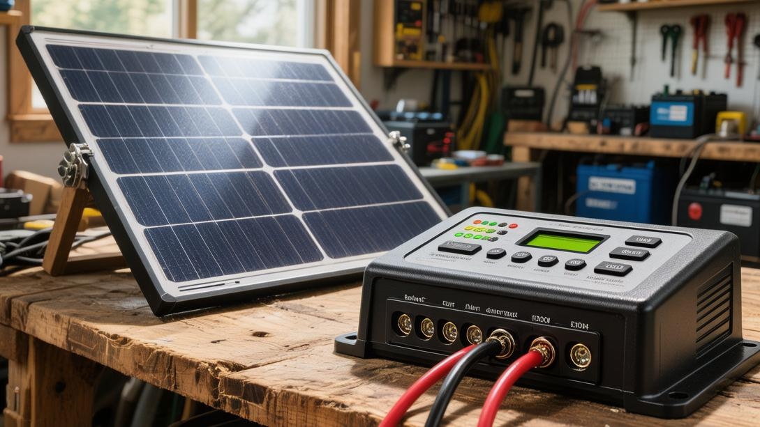
What are the requirements for a solar charge controller
Choosing a controller requires matching the system voltage (e.g., 12V/24V), and the current rating should be at least 25% higher than the maximum panel current to ensure safety.
It is recommended to prioritize an MPPT controller, as its charging efficiency is about 30% higher than the traditional PWM type.
In addition, be sure to confirm that the controller is compatible with your cell type (e.g., lithium or lead-acid) and has comprehensive overcharge and short-circuit protection functions, which is the key to extending cell life and ensuring stable power station operation.
Voltage and Current Compatibility
Leave enough voltage difference
When building a solar system, the rated operating voltage of the controller must cover the entire process from the cell pack's 10.5V discharge cutoff to its 14.6V full charge. For 48V systems, the voltage range fluctuates between 42V and 58.4V.
The voltage withstand value of the internal capacitors usually needs to reach 100 V or 150 V to cope with the instantaneous high-voltage impact generated by the photovoltaic array within 0.1 seconds in the morning.
When choosing an MPPT controller, the solar panel's operating voltage (Vmp) should be at least 2V to 5V higher than the real-time cell voltage, so that conversion efficiency can be maintained at a high level of over 97%.
If the voltage difference is lower than this value, the controller will automatically reduce the frequency or even stop working, resulting in a loss of about 15% of power generation during morning and evening periods.
For a 12V system, it is recommended to choose a solar panel open-circuit voltage between 18V and 24V. For a 48V system, you need to match a photovoltaic array with a total voltage between 60V and 120V to ensure that the charging logic can be triggered normally 365 days a year.
· Typical charging voltage settings for a 12V system are 14.4V (bulk/equalize) and 13.8V (float).
· The static power consumption of the controller in 24V mode is usually controlled between 15mA and 25mA.
· The line loss of a 48V system is 75% lower than that of a 12V system, saving about 30% in cable costs.
· The MPPT startup voltage difference is usually set at cell voltage +2V, and the shutdown difference is +1V.
Withstand the highest voltage
The open-circuit voltage (Voc) of a solar panel increases as the ambient temperature drops. This voltage temperature coefficient is usually between -0.28%/℃ and -0.35%/℃.
Assuming you are using it at an altitude of 2000 meters and the temperature is as low as -20℃, a panel with a nominal 45 V will have an actual open-circuit voltage soaring to around 52 V.
If the maximum input voltage marked on the controller is only 50 V, its internal MOSFET will be permanently damaged by overvoltage breakdown within 10 milliseconds.
To ensure a design life of 20 years, engineers usually reserve a safety factor of 1.2 times based on Voc.
This means for a controller rated at 100V, the actual total series voltage of the connected solar panels should not exceed 80V.
During the high summer temperature of 50℃, the solar panel voltage will drop by about 10%. At this time, if the voltage difference is insufficient, the charging power will drop directly from 100% to below 30%.
· For every 10℃ drop in solar panel Voc, the voltage rises by about 3% to 4%.
· The clamping voltage of the internal TVS tube must be more than 15% higher than the system peak voltage.
· 150V high-voltage controllers are usually 20% to 40% more expensive than 100V controllers.
· In high-altitude areas where the air is thin, the insulation gap of the controller needs an additional 10% safety redundancy.
Keep the current on track
The rated current of the controller (such as 30A, 60A, 100A) refers to its maximum charging capability at the output end, not the short-circuit current of the solar panel.
According to the NEC 690 standard, when choosing a controller, the short-circuit current (Isc) of the solar array should be multiplied by a safety factor of 1.25.
For example, for a 10A solar array, a controller of 12.5A or more must be used. In practice, a 20A specification is often purchased to leave a 37.5% margin.
When the ambient temperature exceeds 45℃, most controllers will start derating protection, and the output current will decay at a rate of 2% per degree.
If the controller remains at 100% full load for a long time, the life of the internal electrolytic capacitor will be shortened from 10,000 hours to less than 3,000 hours.
Running at 70% to 80% of the rated current is a key parameter for extending the controller's usage time to more than 10 years.
· A 60A controller supports a maximum of about 720W power in a 12V system and 2,880W in a 48V system.
· The temperature rise of the controller at full load should be controlled within 35℃, and the shell temperature should not exceed 65℃.
· The accuracy of the current sampling resistor must reach 1%, and the temperature drift coefficient should be below 50 ppm.
· The rated current of the fuse at the output end should be set to 1.25 to 1.5 times the maximum output of the controller.
Thick wires reduce voltage drop
The hole size of the controller terminal directly determines the maximum current density the system can withstand. Usually, a 60A controller is equipped with a 25mm² terminal.
If thin 4 mm² wires are used to connect the controller and the cell to save money, when the current reaches 40 A, every meter of wire will produce a voltage drop of about 0.2 V.
This 0.2V error will cause the controller to mistakenly believe the cell is fully charged, thereby entering the float charge phase early, resulting in the cell remaining undercharged for a long time and shortening the cycle life by 20% to 30%.
When designing the wiring, the distance from the controller to the cell should be shortened to within 1.5 meters, and the total line voltage drop must be controlled within 1% (i.e., 0.12V for a 12V system).
Using tinned copper wire can reduce contact resistance by about 5% and prevent oxidation corrosion in an environment with 90% humidity.
· The temperature rise of 10 AWG wire at 30 A current is about 20℃ to 30℃.
· The resistance value of 25 mm² wire is about 0.727 mΩ/meter, with extremely low loss at high current.
· The tightening torque of screw terminals usually needs to reach 1.2 Nm to 1.8 Nm.
· If the voltage sampling error at the terminal exceeds 0.05 V, it will affect the cell SOC calculation accuracy by about 5%.
Efficiency saves money
The core value of the MPPT controller lies in its peak conversion efficiency of over 98%, which means only 20W of a 1,000W input turns into heat.
In contrast, low-end PWM controllers often have an efficiency of only 70% to 75% when the cell power is low. This 25% energy loss is directly converted into the purchase cost of solar panels.
Calculated at 1.5 RMB per watt of solar panel, a 1,000W system using PWM will waste solar panel power worth 375 RMB.
The inductor coils of high-quality controllers use multi-strand windings, which can effectively reduce the skin effect loss under high-frequency switching, keeping the conversion efficiency above 95% within the load range of 20% to 100%.
Choosing a controller with an ultra-fast tracking speed (less than 1 second) can increase daily power generation by 10% to 15% in cloudy weather compared to ordinary controllers.
· The increase in self-consumption after one hour of full-load operation should not exceed 5W.
· Efficient MPPT can still maintain over 90% efficiency under low light conditions (5% input power).
· For every 1% increase in conversion efficiency, 500 to 1,000 kWh of additional electricity can be generated over a 25-year life cycle.
· The ripple voltage of the controller should be lower than 1% of the rated voltage to protect the lithium cell BMS.
Derate to avoid high temperatures
The junction temperature limit of the power modules inside the controller is usually 150℃. To ensure safety, manufacturers will set the shell protection temperature at 75℃ or 80℃.
For every 1℃ increase in ambient temperature, the maximum allowable output current of the controller will drop by about 1.5 A to 2 A.
For controllers with natural fanless cooling, the area of the aluminum heat sink fins on the back should reach more than 15 square centimeters per ampere.
In a desert or scorching sun environment of 50℃, a 100 A controller may only be able to output 60 A of effective charging current.
By reserving a 15 cm ventilation space above the controller and installing a small 5V 0.5A induction fan, the internal core temperature can be reduced by 15℃, thereby increasing the controller's power output by 10% to 20% and reducing the failure probability of electronic modules by more than 50%.
· The storage temperature range for industrial-grade controllers is usually -40℃ to +85℃.
· When the heat sink temperature reaches 65℃, the smart fan should turn on at 100% speed.
· Increasing the thickness of the aluminum alloy shell by 1 mm can improve heat dissipation efficiency by about 8% to 12%.
· Due to heat accumulation, the temperature inside a sealed electrical box is usually 15℃ to 20℃ higher than the external environment.
Controller Type
Which choice is more cost-effective
An ordinary PWM controller works like a fast-switching switch installed between the solar panel and the cell.
When the cell is nearly full, the frequency of the switch opening increases, thereby limiting the current entry.
The logic of this mode is to force the voltage of the solar array down to near the cell voltage.
For example, for a 100W solar panel with a rated operating voltage (Vmp) of 18V and current (Imp) of 5.5A, when connected to a 12V cell, the PWM will force the panel to operate at about 13V. This means you can only get 13V * 5.5A = 71.5W of power, and 28.5% of the energy disappears at the moment of connection.
For small street lamps or monitoring systems with a budget lower than 200 RMB and total power between 100W and 150W, PWM still has a high cost advantage due to its low unit price of 15 to 30 USD. After all, in small power scenarios, the cost of buying an extra panel may be lower than upgrading the controller.
Typical data:
· PWM conversion efficiency: 70% - 75%
· Hardware cost: Usually 20% - 30% of MPPT
· Applicable power: Recommended to be less than 200W
· Static loss: 3mA - 8mA
High efficiency generates more power
In contrast, the MPPT controller integrates a complex DC-DC conversion circuit with an operating frequency usually between 20 kHz and 100 kHz.
Instead of directly pulling down the voltage of the solar panel, it uses internal inductive modules and control algorithms to find the point where the product of the solar panel's current and voltage is maximized in real time.
Even if the cell voltage is only 12V, MPPT can keep the solar panel at a high-efficiency output state of 18V, and then convert the extra voltage into current through an internal step-down circuit to charge the cell.
This means for the same 100W panel, MPPT can output nearly 98W of power.
In large 48V home energy storage systems, if the solar array reaches 5,000W, using MPPT can produce about 4 to 6 kWh more electricity per day than PWM. At 0.6 RMB per kWh, it can create about 1300 RMB more income per year, and the price difference for upgrading the controller can usually be fully recovered within 24 months.
Performance indicators:
· MPPT tracking efficiency: Above 99.5%
· Peak conversion efficiency: 97% - 99%
· Return on investment (ROI) period: Usually 12 - 24 months
· Typical operating frequency: 40 kHz - 80 kHz
Voltage difference determines returns
In many modern installation cases, to reduce line losses, installers like to connect 3 or 4 37V solar panels in series, so that the system input voltage reaches 110V or even higher to charge a 24V or 48V cell.
In this case, PWM cannot work properly at all because it cannot complete such a large voltage drop and current conversion.
MPPT can easily handle such high voltage difference scenarios. Even at 6 am with very weak light, as long as the solar panel voltage is 2V higher than the cell, it can start the charging logic.
Research data shows that in a low-temperature environment (e.g., -15℃), the solar panel's voltage will increase by more than 10%. At this time, the additional gain of MPPT will soar from the regular 30% to over 45%, which is a lifeline for maintaining system power in areas with insufficient winter sunlight.
Voltage associations:
· Maximum input voltage (Voc): Mainstream specifications are 100V, 150V, 250V
· Morning and evening work gain: Extends charging time by about 1.5 - 2 hours compared to PWM
· Line loss reduction: High voltage input can reduce cable heating loss by about 50%
· Startup voltage threshold: Cell voltage + 2.0V (±0.5V)
Impact of ambient temperature difference
The output power of photovoltaic modules is strongly affected by the ambient temperature. When the roof temperature reaches 65℃, the voltage of the solar panel will drop significantly.
If PWM is used at this time, since it cannot adjust the operating point, the charging current will further shrink, resulting in power generation in summer being 20% lower than expected.
MPPT's intelligent algorithm scans the power curve every 0.5 to 1 second to ensure that every last watt of energy is squeezed out at any temperature.
In addition, high-quality MPPTs are usually equipped with larger aluminum heat sinks, often weighing more than 3 times as much as a PWM of the same current rating. This is to ensure that power modules will not derate output due to overheating in extreme high temperatures of 50℃.
Physical parameters:
· Scanning frequency: Full power path scan once per second
· Temperature compensation coefficient: -3mV/℃/Cell (Lead-acid cell standard)
· Heat sink area: No less than 150 square centimeters of heat dissipation surface per 10 A current
· High temperature derating point: Usually set to start linearly reducing output current at 55℃
Scale determines the choice
Regarding how to decide on a solution based on system scale, there is a recognized balance point in the industry: 300 W.
When the total power of your solar array is below 200W, buying a 40 USD MPPT seems a bit overkill, because the extra 25% of power generation is only about 50W, and it is better to spend that 40 USD on an extra 100W panel to hang on the wall.
But as long as the power exceeds 300W, or the cell voltage reaches 24V or above, MPPT becomes the only reasonable choice.
In 500W to 1,000W medium-sized off-grid systems, since more expensive deep-cycle lithium batteries are required (costing about 800-1200 RMB per kWh), using MPPT is not only for more power generation but also to extend the cycle life of lithium batteries from 3000 to over 5000 cycles through precise staged charging logic (bulk, equalize, float). This indirect saving in cell replacement costs far exceeds the price of the controller itself.
Selection reference:
· Below 200W: Recommended PWM (cost priority, low static power consumption)
· 300W-1000W: Recommended 100V/40A grade MPPT
· Above 2000W: Must use 150V/60A or higher specification MPPT
· Expected system life: High-quality MPPT design life is usually 10 - 15 years
Comprehensive Protection Features
Short-circuit instant cutoff
When an accidental short circuit occurs at the output of the system, the current will soar to more than 10 times the rated value within a few milliseconds.
A qualified controller should be able to identify current abnormality within 10 ms and force the power tube to shut down to avoid melting internal circuits due to instantaneous high temperatures.
If the protection delay exceeds 50 ms, the junction temperature of the internal inductor and MOSFET will rapidly exceed the 150°C limit, leading to permanent equipment failure.
High-quality equipment usually adopts dual current sampling logic with a sampling frequency of no less than 10 kHz to ensure the circuit is locked at the moment a short circuit occurs.
When the fault is cleared, the controller should have an automatic restart mechanism with a delay of 5 to 10 seconds, rather than remaining in a locked state, to ensure the automatic recovery capability of the off-grid system when unattended.
Parameter Index | Performance Requirement |
Protection response time | < 10 ms |
Short-circuit detection frequency | 10000 times/second |
Power tube withstand current | 3-5 times the rated current |
Auto-recovery delay | 5 - 30s adjustable |
No burning when reversed
In actual installation sites, about 5% of installation errors stem from reversed positive and negative poles, especially for terminals without foolproof designs.
Traditional cheap controllers use diodes for anti-reverse protection, but this produces a tube voltage drop of about 0.7V, which will generate about 42W of extra heat at 60A current, seriously reducing efficiency.
Modern professional controllers switch to a low on-resistance MOSFET group (Rds(on) usually below 2 mΩ). This design has almost no energy loss during normal operation but will cut the closed loop within 0.1 seconds of detecting reversed cell polarity.
This protection should cover not only the cell end but also the photovoltaic input end.
For a 48V system, if the solar array is connected in reverse under 150V high voltage, the hardware redundancy of the controller must be able to withstand this reverse voltage impact without breakdown.
Stabilize the voltage
Overcharge protection is a core indicator for extending cell life, and its sampling accuracy directly affects the number of cell cycles.
Taking a 48V lithium iron phosphate cell pack as an example, the upper charging limit of a single cell is usually 3.65V, and the voltage of the entire group is 58.4V.
If the voltage collection error of the controller reaches ±0.5V, it is very easy for the cell pack to be in a micro-overcharged state for a long time, causing its cycle life to plummet from 6000 cycles to below 3500 cycles.
Excellent controllers should control the voltage sampling accuracy within ±0.1V or even higher, and have a temperature compensation function.
When the ambient temperature drops by 1°C, the controller should automatically compensate the charging voltage according to a slope of -3V/Cell/C.
For low voltage disconnect (LVD) protection, the controller should dynamically adjust the cutoff threshold according to the load current to prevent the cell from being completely drained under low load, ensuring that the cell SOC (state of charge) always remains in a safe zone of more than 15%.
Cell Type | Suggested Protection Voltage (12V System) | Accuracy Requirement | Impact on Life (Error > 0.5V) |
LiFePO4 | 14.6V | ±0.05V | Cycle life shortened by 40% |
Ternary Lithium | 12.6V | ±0.03V | Risk of thermal runaway |
Sealed Lead-acid | 14.4V | ±0.1V | Electrolyte dry-out accelerates |
Block high heat
When the controller performs high-current conversion, internal losses will be dissipated in the form of heat.
If the shell heat sink fins are poorly designed, the internal core temperature will soar from room temperature to 80°C within 30 minutes.
Professional-grade controllers must have at least two built-in temperature sensors: one to monitor the power module (MOSFET) and another to monitor the ambient temperature.
When the heat sink temperature reaches 65°C, the controller should automatically start linear current-limiting mode, forcing the output power down by 20% to 30%, rather than cutting off charging directly.
If the temperature continues to climb to 85°C, the system must shut down all outputs within 3 seconds to prevent solder melting or shell deformation.
The area of high-density aluminum extrusion heat sinks should ensure an effective heat exchange surface of no less than 180 square centimeters for every 10 A current, in order to maintain full power output in an outdoor environment of 50°C.
Lightning and surge protection
Off-grid systems are usually installed in open areas and are highly susceptible to induced lightning and grid surges.
High-energy TVS (Transient Voltage Suppression) diodes or varistors must be integrated into the DC input and output terminals of the controller.
The surge resistance energy of these modules should reach the 4000V to 6000V level, capable of discharging lightning current to the ground wire within nanoseconds.
When encountering a standard 8/20 μs lightning wave impact, the protection circuit should be able to absorb at least 600 J of energy without damaging the core logic chip.
In addition, the controller shell must reserve a dedicated grounding terminal, and the grounding resistance should be less than 4 Ω.
Without this protection, a single distant lightning strike induction could produce an instantaneous voltage more than 5 times the controller's withstand voltage, directly breaking down all internal integrated circuits.
Protection Item | Technical Specification | Response Speed |
Surge voltage resistance | 4000V - 6000V | < 1ns |
Maximum absorption power | 600W - 1500W | Instant pulse |
Electrostatic protection (ESD) | 8kV Contact / 15kV Air | Continuous protection |
Night loss prevention
After the sun sets, the solar panel no longer generates voltage. At this time, the cell voltage (e.g., 13V) will be higher than the solar panel voltage.
Without reverse-charging protection, current will flow from the cell to the solar panel at a rate of 50mA to 200mA per hour, causing the solar module to heat up at night and wasting about 5% to 10% of daily power generation.
The controller should have extremely low static power consumption, also known as "self-consumption".
In night standby mode, its self-loss should be controlled within 10 mA (about 0.12 W for a 12 V system).
If self-consumption reaches 50 mA, for a small 20 Ah cell system, the controller standby alone could drain the power in less than 20 days.
By using high-impedance sampling circuits and low-power MCUs, the survival cycle of the system in rainy days can be extended by more than 3 times.